By the mid teens (19-teens), experimenters had realized circuits with gain (amplification – it “gains strength”) and had some knowledge of simple tuned circuits. It led Ernst Alexanderson to develop what we call Tuned Radio Frequency, or TRF, receivers. He patented it in 1916. His concept was that each stage would amplify the desired signal while reducing the interfering ones. Multiple stages of RF amplification would make the radio more sensitive to weak stations, and the multiple tuned circuits would give it a narrower bandwidth and more selectivity than the single stage receivers common at that time. All of the tuned stages of the radio must track and tune to the desired reception frequency.
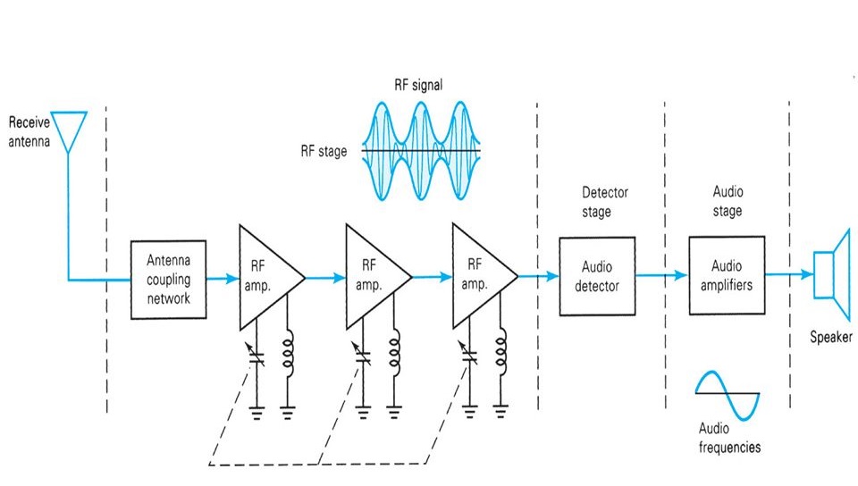
The three stages of Radio Frequency amplification have a single tuning circuit consisting of a parallel inductor/capacitor with the capacitor tunable so the operator can resonate the inductor on the frequency the user wants to listen to. This is a primitive method of filtering, and would be made more sophisticated in later years, but the “network theory” that enabled that hadn't been derived by 1915. A parallel tuning circuit is high impedance (AC resistance) to ground at its tuned frequency, and closer to a short circuit to ground far below or above that frequency. This means it minimizes the loss of the signal at only its tuned frequency while above and below this frequency the signal is shunted more to ground rather than conducted to the next stage. The amplification solved the sensitivity problem with the amplifiers, but there isn't so much gain that the circuit is likely to oscillate (like a microphone amplifier squealing) from strong signals out of the third amplifier leaking back to the input of the first stage.
The TRF did improve performance of the radio, but now a new, previously undiscovered problem existed: getting three separate tuned circuits (an electric filter) to tune over a fairly wide frequency range by tuning only one element in each is a difficult problem, even today. When the circuit is tuned, the amount of rejection of nearby stations varies, getting proportionally more narrow as you tune lower and wider as you tune up in frequency. Getting all three circuits to peak amplification was delicate and required the user to make fine adjustments. That makes this architecture usable only for single frequency applications (or very narrow bands of frequencies).
This is not meant to belittle Alexanderson's work: he succeeded in improving the sensitivity, selectivity and signal handling characteristics of the radio receiver.
Today, TRF receivers are used in niche applications. The first one I ever encountered was a special application in aviation called a marker beacon. You probably know that there are established routes for aircraft into and out of airports. On the landing approach, there are systems that allow automatic landing with three radio systems: the ILS (instrument landing system) localizer, which keeps the aircraft on the centerline of the runway; the Glide slope system that keeps it on a (typically 3 degree) vertical slope to the ground, and a set of Marker Beacons that point vertically to tell the pilot they're on the proper path and where the aircraft is: outer, middle and inner beacons. These are all transmitted at 75.0 MHz, and aren't challenging to receive. The signals are in a convenient range of amplitude and integrated circuit amplifiers available by the 1980s like MC1590 turned these into rather simple receivers. The very first stage of these receivers tends to be a 75.0 MHz crystal filter that is narrow enough to keep nearby strong signals from hitting the detector, and the detector itself is just looking for three audio frequencies, so they are narrowband audio filters.
TRF receivers are also used in some Industrial Scientific and Medical (ISM) applications such as some remote door locks for cars and there are some systems that use it to synchronize “atomic clocks” - the ones that receive the broadcasts from WWVB or other countries' time/frequency standard stations.
Something that's never talked about is that since they have no local oscillator, they have no emissions. They can't be detected by monitoring for the emissions from the radio. They could be usable as a fixed-tuned receiver or for a small number of channels for something like local VHF communication on the six, four (non US) or two meter bands or similar. Running all the stages at VHF will make the detector more challenging, but a small group that only wants to use one frequency (or a couple) might be able to make this work.
Regeneration
Again, the TRF architecture was patented in 1916 and so I'd be sure he had a working model several months before that, possibly in 1915. Before that, Edwin Armstrong developed the Regenerative Detector that allowed great improvements in sensitivity of the receivers. Again, it relied on the gain of the triode.
The trick about regeneration is that it applies feedback to the circuit to improve gain. A short side trip is in order.
It's helpful to describe feedback as positive or negative: positive feedback creates oscillation. This is what you're hearing if someone puts a microphone in front of a loudspeaker. Some little bit of noise gets into the microphone, it comes out of the speaker louder than it went into the amplifier, now the microphone picks up that sound, which goes into the amplifier and gets louder, and at the speed of electronics, the sound goes from barely audible to full volume screaming out of the loudspeaker. For this oscillation to happen, the amplifier just needs the tiniest bit of gain more than 1. Negative feedback is extremely useful in controlling the amount of amplification, by feeding back some of the signal shifted in phase so that it cancels out some of the input and keeps the output constant. Negative feedback wasn't conceptualized until 1927 by Harold Stephen Black of Bell Labs. Today virtually all amplifiers are designed around negative feedback.
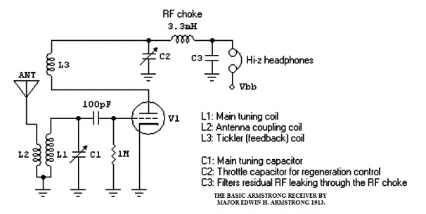
Here's Armstrong's circuit redrawn recently
(source)
L3, called the “tickler coil”, is in the output circuit of the tube so it's an amplified version of the input. By adjusting the distance (which adjusts the coupling) between L3 and L1, the gain of the amplifier could be adjusted until just before it broke out into oscillation, so that any increase in signal made it start to oscillate. At this point, it had maximum gain, and the Armstrong's detector was more sensitive than any existing receiver.
Like the TRF, regenerative receivers are hardly used in commercial receivers because they're touchy and need to be futzed with to keep them working without breaking out in squealing oscillations.
Hobbyists, though, still play with regenerative receivers just as a fun toy. (Example 1, example 2) They have the unique property that by adjusting feedback just below the oscillation, they're a sensitive AM detector, but if put into oscillation, they can demodulate Single Sideband and CW (Morse code transmissions). These are detected in conventional modern radios with a circuit called a product detector, which uses an oscillator (called the Beat Frequency Oscillator) running on a precisely chosen offset frequency. With the offset frequency not set quite right, Single Sideband (SSB) has often been said to sound like Donald Duck – I honestly haven't played with regenerative receivers enough to know if they handle SSB approximately correctly. Regeneration has largely been replaced with other techniques, even in amateur homebrew gear.
I've tinkered a bit through the years with regen sets, and some are very good, and some not so hot, at demodulating SSB. Bruce Vaughn, NR5Q (SK), who used to write for Electric Radio, was quite a whiz at regen and super-regen sets, and had published many designs.
ReplyDeleteThe build a good one takes lots of little tricks, and he'd figured them out to the nth degree. One of these days I might try to reproduce one of Bruce's sets.
Many QRP rigs now use Direct Conversion receivers, and even some of the little "SDR" kits are Direct Conversion to I and Q signals, and then the software takes over.
No fair getting ahead of me ;-) I figured I had to introduce superhets and IF strips before going to Zero-IF radios.
DeleteAnd do we get to talk about the importance of a low noise L.O., and the wonders of mixer products?
Delete