We've covered the development of radio receivers up until the end of the 19-teens, but have never talked about what the receivers are actually receiving. That requires a side track into transmitters that had to wait for us to get past the development of the triode and superheterodyne because modern transmitters use the same basic superheterodyne approach. Suffice it to say that radios were being used for communications long before the advent of modern architecture (superheterodyne) transmitters and receivers.
Single radio frequency generation would rely on the development of the vacuum tube triode oscillator, a circuit that deliberately creates that “microphone in front of the speaker”, positive feedback effect by tapping some of the output and sending it through a circuit back to the input, which tunes the frequency of oscillation. The invention of the oscillator is another of those things credited to Edwin Armstrong. These circuits are most often an inductor/capacitor from output to input. (Since the schematic symbol for an inductor is usually called “L” and a capacitor is called “C”, these are referred to as LC oscillators) All that is needed is a gain of 1 and this positive feedback to ensure the generation of an output at the frequency of the LC circuit. By varying either component, a Variable Frequency Oscillator or VFO could be obtained, and that allowed tuning many frequencies, not just one.
Modulation is the process of adding intelligence to a signal, called the carrier, to communicate over a distance. In its simplest form, a transmitter's output can be keyed on and off, giving the Morse code we hear today (called Continuous Wave modulation or CW), but the goal was to transmit sound – voice and music. Turning the signal on and off is the most extreme form of changing its amplitude, but what if we could vary the amplitude of the transmitter signal with the amplitude of the speech? Of course, this is Amplitude Modulation or AM (and sometimes referred to as “Ancient Modulation” by hams). I'm going to spend a bit of time here on AM and then FM because they're the modes people are most familiar with.
AM modulation can be done at low power levels in the transmitter, but was typically done in the final amplifier stage. Why? If the modulation is done at a low power level, the amplifiers that produce the transmit power can distort the modulation, unless they're run to be “linear”, so that the output signal is an enlarged version of the input. This is an inefficient mode, or "class" – the tube has to run considerably more power than if it's just setup to amplify as much as it can – so designers typically run everything as “wide open” (highest gain) as they can and modulate the output.
A generic low level modulated versus high level (plate modulated) AM transmitter. The block diagrams are very sparse on details; that box labeled “VFO & LO” can be several pages of schematics. In older models, that might be a VFO tuning half or one MHz in the low HF spectrum, say from 5.00 to 6.00 MHz, and a host of crystals to mix with that to generate the desired HF bands. Today, that box might be a single chip Direct Digital Synthesizer for casual use, or a complex Phase Locked Loop synthesizer for the highest performance. On the left, those two RF amplifiers might be four or more stages, all “Class A”, high linearity stages. On the right, there might be more than two stages, but they all would be higher gain, “Class C” stages.
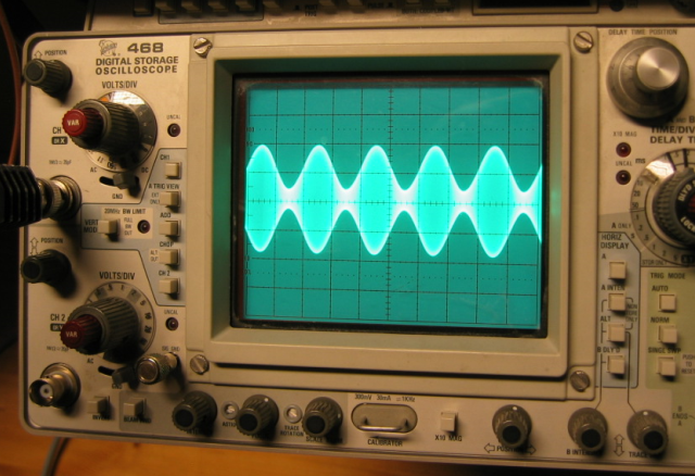
AM as seen on an oscilloscope. The carrier is so much higher in frequency than the audio that we see what looks like an audio frequency envelope filled with lighter color that's the many cycles of the carrier. The amount of AM is measured in percentage and that can be calculated by measuring the amplitude of the peaks and valleys of the signal, my rough guess is this is about 80% modulated.
Any portion of the transmitter's power amplifier circuit can be used to modulate the output amplifier: the cathode, grid or the output (plate); modulators are referred to by what they modulate. I don't follow AM enough to say what the most common mode is, but since plate modulation is running the RF circuits in the most efficient mode possible (class C), I always thought the industry would have used that. A high voltage transformer is used to apply the modulation to the plate circuitry.

Mathematically, AM modulation is mixing: multiplying the carrier times the audio frequency. If the audio includes a DC value of the proper voltage, the output of the circuit is the carrier (the DC term) along with the sum and difference frequencies – the carrier plus the audio and the carrier minus the audio. The sum is referred to as the upper sideband and the difference as the lower sideband. If you think about it a minute, if all the information is in the sidebands, and the same information is in either sideband, the logical conclusion is if you only transmit one sideband you transmit 100% of the information, at a tremendous saving in power. The only thing sending full AM does is make the receiver easier. Bell Labs was researching this in the early 1920s.
As anyone who has listened to an AM radio can tell you, AM is prone to noise pickup. This is because static, electrical sparks, and so much more, cause noise spikes of high amplitude at the receiver frequency and this unwanted AM gets “stuck onto” the desired signal. While Frequency Modulation was experimented with for noise improvement before Armstrong's work, this was work done on narrowband FM and that legitimately doesn't provide as much immunity to noise as the wideband FM that Armstrong patented in 1933. Wideband FM (WBFM) hadn't been properly analyzed by others and they hadn't foreseen some of the benefits of WBFM. Today's Broadcast FM stations are the WBFM that Armstrong originally developed (with the addition of stereo). Because FM detectors are designed to detect changes in frequency rather than amplitude, they are much less affected by AM noise like lightning static, powerline noise and so on. Part of the protection is the use of VHF frequencies for FM broadcast – the sources I just mentioned are naturally reduced in amplitude as the radio frequency goes up.
The amount of modulation in an FM signal is referred to as deviation, expressed as how far the carrier deviates during use. NBFM is used in amateur handheld radios, with a typical deviation of 5kHz peak; the WBFM which broadcasters use is 75 kHz peak, 15 times greater.
In practice, it's impossible to distinguish Frequency Modulation from Phase Modulation, and many typical FM radios are actually phase modulated. If the audio goes through an RC integrator before being modulated, the result is FM (pdf warning). Often, the amount of modulation is calculated to be a fraction of the desired and frequency multiplication increases the deviation.

Frequency multiplication increases the amount of deviation by the multiplication ratio.
Dispensing with more of the details of the historical steps, it is possible to put intelligence on a radio signal by modulating amplitude, frequency, carrier phase or any combination of those. We can control every characteristic of a radio frequency signal and every characteristic can be used to get information from one person to another.
Today, we've developed general purpose modulators that can produce whatever form of modulation is required. These require signals with a 90 degree phase difference between them, referred to as I and Q signals for In-phase and Quadrature-phase signals. Any form of modulation (pdf warning) can be created with the right waveforms on those two signals. Virtually all of these transmitters are done with the low level modulation scheme used on the left in the figure comparing AM transmitters above.
The most common forms of modulation used commercially are probably Bi-Phase Shift Keying and Quad-Phase Shift Keying, BPSK and QPSK respectively, but higher number of phase shifts like 8PSK are common in places. When you hear of a mode like 64 QAM – quadrature AM – this is combination of both phase and amplitude modulation.
If there are general purpose modulators, there are general purpose demodulators.

This takes in an RF or IF signal and an LO, splits the LO so that one side is 90 degrees behind the phase of the other side. These are then multiplied by the RF, which is simply equally power split with both legs in phase with each other. The result is it strips off the I and Q modulations. If the LO equals the tuned RF, this becomes a Zero IF receiver and in most of what's on the market, the I&Q data streams go into Analog to Digital Converters.
If the input is on the right, as I and Q signals, the radio frequency output is on the left, this circuit becomes your general purpose modulator. These are commodity components made and sold by the tens of thousands - or more. And that's just one supplier. They're made in a variety of technologies with the same block diagram.
It might be helpful for you to know that in receivers this circuit is called an image reject mixer, or image reject front end. Last week, during the brief introduction to the Direct Conversion (Zero IF) receiver, I mentioned its drawback of hearing anything on the image frequency at the same level as the desired station. While this won't give unlimited suppression of the image, it can reduce the image 30 to perhaps 45 dB, not shabby at all.
Ah, that takes me right back to my youth in Pensacola and Berlin, it does.
ReplyDelete♪ Thanks for the memories. ♫