Like last week, my already slow pace (compared to more experienced machinists on the forums I watch) slowed farther. Most of that was due to some other things going on in life. The most time consuming of those was researching an antenna project. All of my antenna projects start with the phrase "when it cools off" and cool weather arrived for the first time last weekend, but that's a story for another day. I'll just stick with this topic.
I decided to do the approach I talked about
last time
and clamp the mounting plate rough stock at an angle and then cut it parallel
to the mill table to form the desired angles. Naturally, I first had to
measure those angles and could do so easily in CAD.

First, notice that the long side (on the left) is 18.8 degrees while the shorter side is 19.4 degrees. The angle I really needed to know is what is required to make those inclined sides parallel to the X-axis of the mill table. I circled the angle I need to know and left question marks there, but it's knowable without having to measure it in CAD. If it's not immediately clear, the 18.8 degree angle and the mystery angle are called alternate interior angles and are equal to each other. I realize a lot of people say they never use that middle or high school math they took, but that's what this is. Nothing but applied geometry.
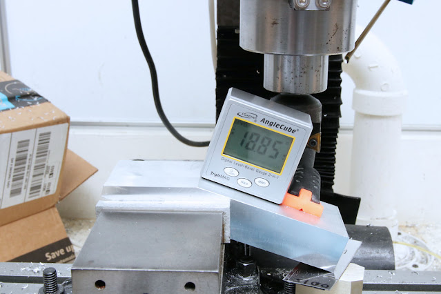
All I had to do was lower the right side (as seen in this drawing) and set the
angle on the inclined surface to 18.8 degrees. The converse goes for the
other side. Long side first (the angle cube is reading 18.85 degrees).
and the short side

I just cut until the very shortest edge was 0.313" and declared it right.
The other issue I mentioned last week is that there are two radius cuts on the bottom and I don't have a cutter of the right size. You can see the two radii in the drawing at the top. I decided the most expedient thing to do is just use the closest drill bit that I have and cut the radii to that size, not the 0.313 radius that drawing calls for. I used a 1/2" drill bit. In that picture at the top, it means drilling into the screen to cut the radius on those two corners. The only thing tricky about this operation is that I'm drilling with the center of the bit on the bottom edge of this piece and drilling holes just doesn't work that way. The way around that is to clamp a sacrificial piece of metal to the work and cut the radius on both pieces. You can see the two half-inch holes in this picture. The eventual mounting bracket is away from the camera, and the sacrificial piece closer to it. I'll need to remove the metal between those two holes - only on the part, not the sacrificial piece.

It shouldn't take more than another few hours in the shop to finish this piece. Which is why I chose it.
Nice job, SiG! I've had to use the sacrificial piece numerous times when making something.
ReplyDelete