It has been a week with too much unwanted adulting, it's the annual insurance renewal time after all, but I did complete the mounting plate I talked about last time.
Top view:
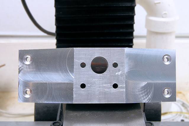
and bottom view:

As you've probably noticed, there are excessive machining marks on the top, and that's kind of sitting on a background processor in my head to try to come up with ways around that. I'm watching a few forum threads by really master machinists and they tend to finish parts before they put the engine together. One guy in particular is building a model of the Ford 300 cubic inch in-line six cylinder engine at about 1/4 scale and his work is so beautiful it blows my mind. He has a bead blaster, another tool I don't have, and every part that will be seen is bead blasted and painted. It makes raw machined parts like this look ugly in comparison. I always thought of them as pretty.
I have some powder coating experience but even though it tends to come out thicker than other finishes, powder coating relies on having the metal itself smoothed and preferably shiny.
The other activity was picking what part to make next. The answer is the next important group of parts: the cylinder, piston, connecting rod, and wrist pin, but probably not in that order. The conventional advise is to make the cylinder as close to perfectly sized as you can determine, then make the piston to fit it. In other words, the cylinder is supposed to be 1.000" inside diameter, but if I make it a little too big or too small, it's still usable if the piston is custom fit to the cylinder. The engine is designed for a polymer piston ring in contrast with the cast iron rings I bought for the Webster last year. The connecting rod has to fit the journal on the crankshaft I just built and it can be sized to that bearing in the same sort of way: the journal size is what it is and I just make the connecting rod to fit.
The cylinder will be made from cast iron, and the finished outside diameter is to be 1.750". My stock is a square bar that's sold as 2" on a side, but is closer to 2-1/16". I plan to cut that down to a slightly oversized square bar, perhaps .050" over on a side, and then mill away some of the protruding corners so that it's easier on the lathe than turning the rectangular crankshaft bar was. Every revolution of the bar as the lathe spun whacked the cutting tools loudly.
I should probably have the connecting rod made before I try to fit the piston into the cylinder. I'm going to need a handle and that's its job in the engine.
Meanwhile, though, it's what we used to call the short week. There will be a couple of days of holidaying so no telling what I'll be able to do. SpaceX has no road closures until next Monday the 29th - and those slip all the time. It figures to be a slow week in everything.
LIVE STREAM: Waukesha officials are giving another update after an SUV plowed into a holiday parade crowd
ReplyDeletehttps://commoncts.blogspot.com/2021/11/live-stream-waukesha-officials-are.html
This part is a stand, and those angled surfaces are just clearance cuts, right? Sandpaper and a wooden sanding block will make those machining marks disappear, to be replaced by sanding marks all running the same direction and looking like an intentional finish. Every outside surface could be treated by sandpaper, Scotchbrite of various grades, polishing, or jeweling. On moving parts like gun bolts jeweling is functional, as the surface pattern holds oil in its grooves which doesn't get wiped off by the slow sliding action.
ReplyDeletehttps://www.cnccookbook.com/guilloche-rose-engines-jeweling-engine-turning-artistic-machining/
https://hackaday.com/2019/03/11/engine-turning-aluminum-the-easy-way/
You're a real craftsman.
ReplyDeleteThis comment has been removed by the author.
ReplyDeleteYou could also try using a small cup wire brush on the mill to make a fish scale finish like used to be popular on shotguns.
ReplyDeleteOn the cylinder, go ahead and cut it all the way down to a regular octagon while you have it set up on the mill, don't just whack off some of the sharp corners. Then the turning will go smooth as silk.
On the cylinder, go ahead and cut it all the way down to a regular octagon while you have it set up on the mill, don't just whack off some of the sharp corners.
DeleteExactly what I was planning. The mental hurdle is getting it to sit at 45 degrees in the vise.
/\
/ \
\ /
\/
(not square but ASCII graphics - you get the idea)
Currently thinking about printing a little Vee block to hold it like that.