If you thought the supercharged V10 we talked about in September was cool; modeler mayhugh1 did a quarter scale V12 Merlin engine, based on some castings he was able to acquire. The castings are gorgeous and the engine improved them.
The Merlin was the engine used in Brtain's famed WWII Spitfire fighters and then adopted into the US' P-51 Mustang.
Full build thread here. It's 84 pages, following the build from February of 2015 through November of '17, and this start up video is on page 80, dated August 28 of '17.
As for my next project, it's not that cool, but it's a step along the way. I'm building a fire eater engine from the book The Shop Wisdom of Philip Duclos. No castings will be involved, just pieces of metal bar stock. There are a few videos of them in action; here's a short one.
These are known as atmospheric engines, vacuum engines, flame eaters, flame lickers, and I'm sure there are names I don't know. I like to call them external combustion engines because of the little alcohol lamp outside the cylinder that powers them. To start it, we flip the flywheel, and as the piston starts to move out of the cylinder, the engine sucks in the flame. Expanding hot air helps push the piston away and a flap covers the input port keeping air from rushing in. The air in the cylinder rapidly cools as it pushes the piston out and after the flywheel finishes that half rotation, the atmospheric pressure outside the cylinder forces the piston back toward the top of the cylinder (the reason they're called atmospheric engines), when the flap opens and allows the flame to be sucked in again.
Some of the videos feature someone trying to get the engine to run reliably for a couple of minutes, and I can imagine the inventors thinking, "if only we could get that combustion inside the engine, maybe we could get it to run more reliably. Some kind of internal combustion..." One of the model makers' websites says the first patent on one of these engines was granted to a Henry Wood in 1758. That predates the Otto engine by a hundred years, which is generally called the first four stroke, internal combustion engine.
Saturday, February 10, 2018


Friday, February 9, 2018
Time for Our Annual Pilgrimage to Orlando
Orlando is best known as home to Walt Disney World, Sea World, Universal Studios and a few other
theme parks, but no mice, killer whales, or movie characters were
involved. Today was our annual visit to the Orlando Hamcation, which we have been doing without missing a year since 1982. The Hamcation's website says that they are now the number two hamfest in the country, behind the Dayton Hamvention. "Dayton" is now Dayton in name only; the hamfest moved to Xenia, Ohio last year when the city of Dayton closed the convention center/arena where it had been held, and Hamvention won't be in Dayton for the foreseeable future.

(A view across the north hall, one of three halls full of displays, in 2017 - Orlando Hamcation photo)
As we did last year for the first time, we decided to attend on Friday this year. The major hamfests seem to be selling themselves more as vacations than for locals, so if one is taking time off from work to travel hundreds of miles to a ham radio convention, taking the extra day to go on Friday vs. Saturday isn't a big deal, and Sundays have been marginal at best at hamfests for as far back as I can recall. The most crowded days are going to remain Saturdays. Going on Friday, we got excellent parking, crowds are much easier to live with, and the whole experience is just better.
What was familiar was: essentially everything. There was the usual collection of old radios, some in use for over half a century, along with radios from every decade since then. If anything, a larger number of dealers were selling the various brands of Chinese VHF/HF handie talkies like Baofeng, Wouxun and others. That said, there were some new radios on display and I stopped for literature at a few place.
Speaking as a guy who spends a lot of time running a barbecue smoker, the folks who do the barbecue there put up a fine lunch. $8 for a stuffed brisket or pulled pork sandwich is really in line with what you pay in a sit-down restaurant, and it's good barbecue.
There were predictably more drones for sale. What was missing was that there didn't appear to be any big product announcements going on. I saw fewer Arduino project kits although they remain well-supported, and given that I've probably seen a dozen web-based projects that made a CNC-driven laser wood burner out of a DVD drive LED, I expected to see something like that. Nope. Likewise, not a single 3D printer.
The weather was good; while it peaked out at around 80 maybe 82, the skies held enough clouds to keep the sun from beating down too much while not giving any rain. The only things I picked up were some accessories for the station, especially while testing things: coaxial connector adapters and some test cables.

(A view across the north hall, one of three halls full of displays, in 2017 - Orlando Hamcation photo)
As we did last year for the first time, we decided to attend on Friday this year. The major hamfests seem to be selling themselves more as vacations than for locals, so if one is taking time off from work to travel hundreds of miles to a ham radio convention, taking the extra day to go on Friday vs. Saturday isn't a big deal, and Sundays have been marginal at best at hamfests for as far back as I can recall. The most crowded days are going to remain Saturdays. Going on Friday, we got excellent parking, crowds are much easier to live with, and the whole experience is just better.
What was familiar was: essentially everything. There was the usual collection of old radios, some in use for over half a century, along with radios from every decade since then. If anything, a larger number of dealers were selling the various brands of Chinese VHF/HF handie talkies like Baofeng, Wouxun and others. That said, there were some new radios on display and I stopped for literature at a few place.
Speaking as a guy who spends a lot of time running a barbecue smoker, the folks who do the barbecue there put up a fine lunch. $8 for a stuffed brisket or pulled pork sandwich is really in line with what you pay in a sit-down restaurant, and it's good barbecue.
There were predictably more drones for sale. What was missing was that there didn't appear to be any big product announcements going on. I saw fewer Arduino project kits although they remain well-supported, and given that I've probably seen a dozen web-based projects that made a CNC-driven laser wood burner out of a DVD drive LED, I expected to see something like that. Nope. Likewise, not a single 3D printer.
The weather was good; while it peaked out at around 80 maybe 82, the skies held enough clouds to keep the sun from beating down too much while not giving any rain. The only things I picked up were some accessories for the station, especially while testing things: coaxial connector adapters and some test cables.
Thursday, February 8, 2018
A Little Machine Shop Steam Engine Puzzle
I've done some experiments with my little "steam" wobbler engine over the course of the last week. I tried it with three different flywheels. As always, there's a story behind this, but first, if you're so inclined, here's a four minute video that shows the experiments.
The video is a combination of three separate videos. The first video is the solid one in that's mounted on the motor in the still photo thumbnail you should be seeing. That flywheel is actually a remake of the first flywheel, which is the one on the left with the six half-inch holes in it, and I posted when I drilled the holes using my rotary table. That flywheel was on the engine in the video I posted in that link at the top. The brass (bronze?) wheel is smaller than the others, 2" diameter instead of 2-1/2". The weights of the solid aluminum flywheel and that one are within 6 grams of each other, but the important mechanical property is the moment of inertia, and I haven't calculated that.
What's the bottom line? As of the moment, I like the looks of the lightweighted aluminum best, and the solid aluminum one the least, but the solid aluminum wheel is on the engine for now. It wobbles more (visible in the first video) and despite that it runs best down to the lowest pressures (12 or 15 PSI).
The engine is "touchy", the tightness of the flywheel is critical. Right now, there's about .010 gap between the upright and the flywheel and it runs well. If I adjust that gap so that there's virtually none, the engine won't run.
 In this view, it looks like they're solidly against each other, and the same with the crank wheel on the other side. If they're that close, I can't get it to run.
Comments invited, of course.
The video is a combination of three separate videos. The first video is the solid one in that's mounted on the motor in the still photo thumbnail you should be seeing. That flywheel is actually a remake of the first flywheel, which is the one on the left with the six half-inch holes in it, and I posted when I drilled the holes using my rotary table. That flywheel was on the engine in the video I posted in that link at the top. The brass (bronze?) wheel is smaller than the others, 2" diameter instead of 2-1/2". The weights of the solid aluminum flywheel and that one are within 6 grams of each other, but the important mechanical property is the moment of inertia, and I haven't calculated that.
What's the bottom line? As of the moment, I like the looks of the lightweighted aluminum best, and the solid aluminum one the least, but the solid aluminum wheel is on the engine for now. It wobbles more (visible in the first video) and despite that it runs best down to the lowest pressures (12 or 15 PSI).
The engine is "touchy", the tightness of the flywheel is critical. Right now, there's about .010 gap between the upright and the flywheel and it runs well. If I adjust that gap so that there's virtually none, the engine won't run.

Comments invited, of course.
Wednesday, February 7, 2018
A Little More Antennas 101 - Part 3
One of the conclusions I had last time was:
This is a plot of a computer simulation of a 7 MHz (40m) half wave dipole. The simulation on the left is with the antenna 66' above the ground, a half wavelength. You can see the radiation peaks are about 35 degrees above the ground. The simulation on the right is with the antenna 1 foot above the ground and you can see the main radiation is straight up. Instant NVIS. Just put your antenna on the ground (or close to it - I can't tell the plots apart with the antenna 6' up). The software, as you can read in the upper right, is the free demo version of EZNEC. The demo version is perfectly adequate for even a few dipoles or monopoles, and is free. Antenna modeling is a whole 'nother world that could take days to go over.

The thing is, this doesn't have to be a separate antenna, if you can raise and lower an existing dipole you can make any dipole into an NVIS antenna. Raise and lower one with pulleys on poles?
All simulations like this are never going to be right if you have your antenna in the midst of trees, or surrounded by things like a metal roof - which is a perfect ground at frequencies where the antenna is around half the dimension (length or width) of the roof. Fun fact: guys who study the effects of things close to the antenna say living trees are more like a person in the field than lumber. Trees are full of water, more like people than lumber, which is dried.
Pattern distortion is an especially big concern for vehicle-mounted antennas. Trunk mounted antennas are very popular for mobile operating. The roof is a better mounting spot (if you can get in your garage!). Lots of money has been spent on simulating and measuring antenna patterns on vehicles by militaries and governments all over the world. You may think you're getting a wonderful, clean, little doughnut pattern like theory says, but when you put it on your car, if the base of the antenna isn't several wavelengths away from metal, you probably get a lumpy, bumpy pattern with all sorts of weaker and stronger points in it.

Field from a rod antenna on the roof of a car; advertising post by EMCoS Warmer colors (red, orange...) denote stronger fields, cool colors (green to blue) denote weaker fields. This is actually pretty good, but the antenna is on the roof.
Finally, should you be concerned about SWR - Standing Wave Ratio (pdf warning)? I'm of the opinion that hams worry too much about this but I also know most solid state radios reduce their output power to protect themselves from the reflected power and some shut down at lower reflected powers than others. I have a radio with a builtin antenna tuner, and I have an external antenna tuner; I use them without hesitation. If my radio is happy, I'm happy. It's true that the best place for a tuner is at the antenna, but I don't personally have the budget of an aircraft developer, all of whom build in an antenna tuner at the bottom of all their HF antennas as part of the aircraft design. The main disadvantage of an SWR that's "too high" is that power is lost in the antenna's feed cable.
When the impedance isn't matched, some of the power delivered to the antenna reflects back to the transmitter. Let's say 5% as a rough number. That 5% gets back to the antenna nanoseconds later and gets reflected toward the antenna; again, let's say 5%. That means almost all (95%) of the 5% gets added to the transmitter's signal and goes back to the antenna. This repeats. There's a technique called a lattice diagram that illustrates this, but the conclusion is that the only power that doesn't make it out of the antenna is the power lost in the cable. Good quality, low-loss cable is worth it.
Antennas can be mind-bogglingly hard to measure in the field, because of the way they interact with the everything. Antenna design is a perfect example of the inflexibility of the laws of physics. There's over a hundred years worth of experience with them to learn some lessons from.
- All antennas have a radiation pattern and a gain.
This is a plot of a computer simulation of a 7 MHz (40m) half wave dipole. The simulation on the left is with the antenna 66' above the ground, a half wavelength. You can see the radiation peaks are about 35 degrees above the ground. The simulation on the right is with the antenna 1 foot above the ground and you can see the main radiation is straight up. Instant NVIS. Just put your antenna on the ground (or close to it - I can't tell the plots apart with the antenna 6' up). The software, as you can read in the upper right, is the free demo version of EZNEC. The demo version is perfectly adequate for even a few dipoles or monopoles, and is free. Antenna modeling is a whole 'nother world that could take days to go over.

The thing is, this doesn't have to be a separate antenna, if you can raise and lower an existing dipole you can make any dipole into an NVIS antenna. Raise and lower one with pulleys on poles?
All simulations like this are never going to be right if you have your antenna in the midst of trees, or surrounded by things like a metal roof - which is a perfect ground at frequencies where the antenna is around half the dimension (length or width) of the roof. Fun fact: guys who study the effects of things close to the antenna say living trees are more like a person in the field than lumber. Trees are full of water, more like people than lumber, which is dried.
Pattern distortion is an especially big concern for vehicle-mounted antennas. Trunk mounted antennas are very popular for mobile operating. The roof is a better mounting spot (if you can get in your garage!). Lots of money has been spent on simulating and measuring antenna patterns on vehicles by militaries and governments all over the world. You may think you're getting a wonderful, clean, little doughnut pattern like theory says, but when you put it on your car, if the base of the antenna isn't several wavelengths away from metal, you probably get a lumpy, bumpy pattern with all sorts of weaker and stronger points in it.
Field from a rod antenna on the roof of a car; advertising post by EMCoS Warmer colors (red, orange...) denote stronger fields, cool colors (green to blue) denote weaker fields. This is actually pretty good, but the antenna is on the roof.
Finally, should you be concerned about SWR - Standing Wave Ratio (pdf warning)? I'm of the opinion that hams worry too much about this but I also know most solid state radios reduce their output power to protect themselves from the reflected power and some shut down at lower reflected powers than others. I have a radio with a builtin antenna tuner, and I have an external antenna tuner; I use them without hesitation. If my radio is happy, I'm happy. It's true that the best place for a tuner is at the antenna, but I don't personally have the budget of an aircraft developer, all of whom build in an antenna tuner at the bottom of all their HF antennas as part of the aircraft design. The main disadvantage of an SWR that's "too high" is that power is lost in the antenna's feed cable.
When the impedance isn't matched, some of the power delivered to the antenna reflects back to the transmitter. Let's say 5% as a rough number. That 5% gets back to the antenna nanoseconds later and gets reflected toward the antenna; again, let's say 5%. That means almost all (95%) of the 5% gets added to the transmitter's signal and goes back to the antenna. This repeats. There's a technique called a lattice diagram that illustrates this, but the conclusion is that the only power that doesn't make it out of the antenna is the power lost in the cable. Good quality, low-loss cable is worth it.
Antennas can be mind-bogglingly hard to measure in the field, because of the way they interact with the everything. Antenna design is a perfect example of the inflexibility of the laws of physics. There's over a hundred years worth of experience with them to learn some lessons from.
Tuesday, February 6, 2018
Hat Tip to SpaceX
SpaceX's flagship Falcon Heavy apparently had a fully successful test flight today, boosting Elon Musk's own Tesla Roadster into orbit and recovering both of the strap-on Falcon 9 boosters. As I'm writing this, a successful recovery of the central Falcon 9 first stage is not confirmed. It's pretty common for the turbulence of the landing to cause loss of the signal, but that has typically come right back. If an antenna was damaged, that would make it difficult to know. The drone ship "Of Course I Still Love You" is unmanned during a landing, but a crew boards it later to secure the booster. I don't know the protocol for how long they wait before doing that.
The two side boosters of the first stage have flown before. One launched the Thaicom 8 communications satellite in May 2016, and the other lofted a Dragon cargo ship to the ISS for NASA in July 2016, according to SpaceX.
View from the VAB of launch complex 39A.
 The view from my backyard.
 The Falcon heavy is the most powerful rocket to launch from the US since the Apollo Saturn V days. SpaceX says
EDIT 2/6/18, 1921 EST: From Spaceflight Now: "Speaking to reporters at the Kennedy Space Center, Elon Musk says the Falcon Heavy's center core did not survive its descent to SpaceX's drone ship in the Atlantic Ocean."
Hopefully, more later.
The two side boosters of the first stage have flown before. One launched the Thaicom 8 communications satellite in May 2016, and the other lofted a Dragon cargo ship to the ISS for NASA in July 2016, according to SpaceX.
View from the VAB of launch complex 39A.


When Falcon Heavy lifts off, it will be the most powerful operational rocket in the world by a factor of two. With the ability to lift into orbit nearly 64 metric tons (141,000 lb)--a mass greater than a 737 jetliner loaded with passengers, crew, luggage and fuel.At this time, SpaceX has said the upper stage has performed two of its three scheduled burns with the last scheduled around 5 hours after the last burn, or around 9:30 EST tonight.
Falcon Heavy's first stage is composed of three Falcon 9 nine-engine cores whose 27 Merlin engines together generate more than 5 million pounds of thrust at liftoff, equal to approximately eighteen 747 aircraft. Only the Saturn V moon rocket, last flown in 1973, delivered more payload to orbit.
EDIT 2/6/18, 1921 EST: From Spaceflight Now: "Speaking to reporters at the Kennedy Space Center, Elon Musk says the Falcon Heavy's center core did not survive its descent to SpaceX's drone ship in the Atlantic Ocean."
Hopefully, more later.
Monday, February 5, 2018
The Las Vegas Shooting And the Ammo Seller Arrest
It took me a while to tease out of this story what I think is going on. The news story is summarized on Ammoland's website. Their article pretty much echoes what little I saw on the national news.
The headlines also scream he was manufacturing armor piercing rounds without a license. As far as I can tell, there is no special license for manufacturing armor piercing ammunition, or even tracers, just a general prohibition against manufacturing armor piercing ammo (for which there are too many definitions) unless it's for sale to the US government or export (18 U.S. Code § 922 A 7). There's a general requirement to be licensed if manufacturing ammunition and reselling it. It seems likely that Haig had what the IRS calls a hobby business, which is one that isn't the owner's livelihood, and that some people keep so they can successfully get reimbursed for the expenses of their hobby. (I've known several people over the years that sold things they made to help pay for their hobbies). All the sources say Haig is an "aerospace engineer" with the reload business on the side. The ATF website shows the following:
I suspect Haig is in the gap between recovering the cost of his hobby and truly making it his livelihood and they're getting ready to hang him so that they can say "we got someone".
 Douglas Haig
Of course, if any of you know more or better, the floor is yours!
Authorities have charged Douglas Haig, 55, of Mesa Arizona with selling “armor-piercing ammunition” to Las Vegas killer Stephen Paddock according to court documents acquired by the Associated Press. Haig works full time as an aerospace engineer and part-time as a manufacturer of reloaded ammunition.The story said the local police recovered tracer rounds from Paddock's room, and traced them back to Haig by fingerprint.
According to the court documents police also found unfired armor-piercing rounds within the hotel room. Law enforcement was able to lift a fingerprint off one of the armor-piercing cartridges. Douglas Haig matched that print and was named a person of interest in the case after law enforcement found his name, and address on a box that was in Paddock's possession.David Codrea links to the actual court document. There is one charge.
...
Haig and his lawyer, Marc Victor, held a press conference on Friday claiming that Haig was innocent. According to Haig, he met a well-dressed Paddock at a gun show in Phoenix, Arizona. He stated Paddock wanted to more [SIC] tracer rounds than he had on hand at the show, so Paddock called him a few days later to set up a sell of 720 tracer rounds at Haig's house.
....
Haig further claims that Paddock did not use his ammunition in the attack because he only sold him tracer rounds.
Conspiracy to Manufacture and Sell Armor-Piercing AmmunitionSo the headlines typically shout he was arrested for manufacturing armor piercing rounds and never mention tracers. I don't have to tell this audience that when the terms "armor piercing" and "tracers" are used, "one of these things is not like the other". The police are saying he manufactured the armor-piercing rounds and got one of Haig's fingerprints off one, but Haig claims he never sold Paddock anything except tracer rounds. The court filing says they were .308 rounds "metallurgically classified as armor piercing incendiary" by some definition. Does that mean Haig considered them tracers but the FBI lab said they were armor piercing, too?
(18 U.S.C. 371, 922(a)(7),(a)(8) and 924(a)(1)(D))
The headlines also scream he was manufacturing armor piercing rounds without a license. As far as I can tell, there is no special license for manufacturing armor piercing ammunition, or even tracers, just a general prohibition against manufacturing armor piercing ammo (for which there are too many definitions) unless it's for sale to the US government or export (18 U.S. Code § 922 A 7). There's a general requirement to be licensed if manufacturing ammunition and reselling it. It seems likely that Haig had what the IRS calls a hobby business, which is one that isn't the owner's livelihood, and that some people keep so they can successfully get reimbursed for the expenses of their hobby. (I've known several people over the years that sold things they made to help pay for their hobbies). All the sources say Haig is an "aerospace engineer" with the reload business on the side. The ATF website shows the following:
Is a person who reloads ammunition required to be licensed as a manufacturer?There's a long gap between selling for profit and selling for the purpose of one's livelihood. This is a gray area: let's say someone shoots your reloads and likes them, so they offer to buy the components and give you a few bucks to do the work. It's hard to argue that's making a profit. How many people have arrangements with neighbors along the lines of "if you cut my lawn for me or shovel my driveway I'll give you a few bucks". It's not livelihood, but if the BATFE wants to argue it's for profit, they have the infinite checkbook of the federal government.
Yes, if the person engages in the business of selling or distributing reloads for the purpose of livelihood and profit.
No, if the person reloads only for personal use.
I suspect Haig is in the gap between recovering the cost of his hobby and truly making it his livelihood and they're getting ready to hang him so that they can say "we got someone".

Of course, if any of you know more or better, the floor is yours!
Sunday, February 4, 2018
A Little More Antennas 101 - Part 2
Yesterday, I mentioned that non-resonant antennas are used all the time and that they can be made to accept power better with devices called manual or automatic antenna tuners that transform the impedance of the antenna to the preferred value. The ratio of the transmitter's designed load impedance to the antenna's impedance gives us something called the standing wave ratio. There are a few ways to think of SWR, but I find it best to think of it as an impedance ratio, and the antenna tuner as an impedance transformer.
You'll find that most transmitters are designed to operate with a transmission line system of 50 ohms, and it's a circuit law that the best power transfer occurs when the transmitter, cable and antenna are all matched to that 50 ohms. The antenna tuner can transform the impedance the transmitter sees at the end of the cable to something closer to 50 ohms so that full power can be transferred.
Antennas convert the power that's delivered to the terminals into electromagnetic waves; they also convert electromagnetic waves that strike the antenna into (much smaller) received powers. They don't do this equally in all directions and there are two concepts to introduce here that so intertwined, they're almost one and the same. The standard dipole antenna has a pattern that looks like a squished sphere; the radiated signal is weaker straight up and straight down than it is toward the horizon. The pattern is shaped sort of like a doughnut. This illustration, from an old Byte magazine article, shows it well.
 The wire is vertical in the top illustration (red), so the pattern is
strongest broadside to the wire and at right angles to the direction the
wire runs. The bottom left is looking at the end of the wire, sticking into and out of the screen. This pattern is with the antenna alone in the universe (or not within a few wavelengths of anything else). The pattern will be distorted in your yard or any real place, unless you have it very high and far away from other things.
The wire is vertical in the top illustration (red), so the pattern is
strongest broadside to the wire and at right angles to the direction the
wire runs. The bottom left is looking at the end of the wire, sticking into and out of the screen. This pattern is with the antenna alone in the universe (or not within a few wavelengths of anything else). The pattern will be distorted in your yard or any real place, unless you have it very high and far away from other things.
I want to call your attention to the blue numbers on the bottom. It says the dipole has gain of 2.17 dB, that is, it's 1.65 times stronger than the reference. (It doesn't say dBi but that's pretty much the published gain of a dipole compared to a perfect isotropic antenna, radiating equally in a sphere.) I talked about this concept in the article on radio charging batteries. The dipole only has gain compared to one of these imaginary, isotropic radiators. The radiation pattern of a quarter wave vertical is very similar, except that in the side view (bottom right) it cuts off at zero degrees elevation because that's the reflecting ground plane under the vertical. Ideally (perfect reflecting ground), it has maximum gain toward the horizon. The gain of the quarter wave monopole depends on how big that perfect reflecting ground under the antenna is, and can actually exceed the dipole gain.
Antenna gain always works to create gain by forcing signal from some directions into another. It's the same way as you can squeeze a balloon and force more air in one place by making the part you're squeezing smaller. In the case of the dipole over the isotropic radiator, the signal that would go straight up or down is pushed out around the perimeter. It has less gain than the isotropic radiator along the up/down axis (bottom right) and more around the edges of the doughnut. Imagine having a spherical balloon and you squeeze it vertically, making it smaller top to bottom; it will get larger in diameter.
A commonly used antenna takes several half wave dipoles and by spacing them properly, along with making them slightly longer or slightly shorter, produces gain in one direction. This is called a Yagi array (more properly a Yagi-Uda array) named for the researcher(s) who developed this almost 100 years ago (1926).
 (source)
Notice that the biggest part of the pattern, the front lobe, goes past 10 to perhaps 15 or 16 dB. Compared to what? Gain is always a comparison between two things, so with nothing noted in the drawing we just don't know, but as I said in that battery-charging article, it's probably dBi because it produces bigger numbers than dB compared to a dipole and bigger numbers sound better.
Let's say that's 15 dB gain, which in linear terms is 31.6 times. If I put 100 watts into the antenna, how much power is in that lobe? If I put 100 watts into the antenna, it puts 100 watts into that lobe. (Yes, that was a trick question) That gain of 31.6 times only means that compared to an isotropic radiator the signal is 31.6 times stronger. An antenna can't add power, adding power requires power. All the antenna can do is squeeze signal from other directions and force it to the front. Notice that there are lobes on the back of the antenna and all of them are weaker than -10 dB; 1/10 of the power is in the strong points off the back of the antenna. That's the power that got pushed into the main, 15 dB-gain lobe.
Think about those battery charging systems again; they might like to generate pencil-point sharp radiation patterns, but if they're radiating power levels that are safe, all they can do is minimize the power in unwanted directions. They can't increase the power delivered to the thing being charged with any antenna tricks.
Quick summary:
 Example of an antenna that's 3/2 (three halves) wavelength long, center fed. The pink traces show the current peaks in the center, nulls at 1/4 wave (just between the first two nulls is a 1/2 wave dipole) and then repeat an additional half wave on each side. This is the popular G5RV antenna. This shows that antennas that are an odd number of quarter wavelengths on a side still fit the signal well. They also produce impedances near the desired 50 ohms. The drawback is that as the antenna gets longer, the radiation pattern changes to something less like a doughnut. The pattern turns into lobes along the wire getting closer to the wire as the wire gets longer.
You'll find that most transmitters are designed to operate with a transmission line system of 50 ohms, and it's a circuit law that the best power transfer occurs when the transmitter, cable and antenna are all matched to that 50 ohms. The antenna tuner can transform the impedance the transmitter sees at the end of the cable to something closer to 50 ohms so that full power can be transferred.
Antennas convert the power that's delivered to the terminals into electromagnetic waves; they also convert electromagnetic waves that strike the antenna into (much smaller) received powers. They don't do this equally in all directions and there are two concepts to introduce here that so intertwined, they're almost one and the same. The standard dipole antenna has a pattern that looks like a squished sphere; the radiated signal is weaker straight up and straight down than it is toward the horizon. The pattern is shaped sort of like a doughnut. This illustration, from an old Byte magazine article, shows it well.

I want to call your attention to the blue numbers on the bottom. It says the dipole has gain of 2.17 dB, that is, it's 1.65 times stronger than the reference. (It doesn't say dBi but that's pretty much the published gain of a dipole compared to a perfect isotropic antenna, radiating equally in a sphere.) I talked about this concept in the article on radio charging batteries. The dipole only has gain compared to one of these imaginary, isotropic radiators. The radiation pattern of a quarter wave vertical is very similar, except that in the side view (bottom right) it cuts off at zero degrees elevation because that's the reflecting ground plane under the vertical. Ideally (perfect reflecting ground), it has maximum gain toward the horizon. The gain of the quarter wave monopole depends on how big that perfect reflecting ground under the antenna is, and can actually exceed the dipole gain.
Antenna gain always works to create gain by forcing signal from some directions into another. It's the same way as you can squeeze a balloon and force more air in one place by making the part you're squeezing smaller. In the case of the dipole over the isotropic radiator, the signal that would go straight up or down is pushed out around the perimeter. It has less gain than the isotropic radiator along the up/down axis (bottom right) and more around the edges of the doughnut. Imagine having a spherical balloon and you squeeze it vertically, making it smaller top to bottom; it will get larger in diameter.
A commonly used antenna takes several half wave dipoles and by spacing them properly, along with making them slightly longer or slightly shorter, produces gain in one direction. This is called a Yagi array (more properly a Yagi-Uda array) named for the researcher(s) who developed this almost 100 years ago (1926).

Notice that the biggest part of the pattern, the front lobe, goes past 10 to perhaps 15 or 16 dB. Compared to what? Gain is always a comparison between two things, so with nothing noted in the drawing we just don't know, but as I said in that battery-charging article, it's probably dBi because it produces bigger numbers than dB compared to a dipole and bigger numbers sound better.
Let's say that's 15 dB gain, which in linear terms is 31.6 times. If I put 100 watts into the antenna, how much power is in that lobe? If I put 100 watts into the antenna, it puts 100 watts into that lobe. (Yes, that was a trick question) That gain of 31.6 times only means that compared to an isotropic radiator the signal is 31.6 times stronger. An antenna can't add power, adding power requires power. All the antenna can do is squeeze signal from other directions and force it to the front. Notice that there are lobes on the back of the antenna and all of them are weaker than -10 dB; 1/10 of the power is in the strong points off the back of the antenna. That's the power that got pushed into the main, 15 dB-gain lobe.
Think about those battery charging systems again; they might like to generate pencil-point sharp radiation patterns, but if they're radiating power levels that are safe, all they can do is minimize the power in unwanted directions. They can't increase the power delivered to the thing being charged with any antenna tricks.
Quick summary:
- Antennas work best when the radio wave mechanically fits the antenna.
- The mechanical size of the wave gets smaller as the frequency goes up.
- That often leads to having different antennas for every band you're interested in.
- Antennas can be used on bands other than the ones that fit perfectly with antenna impedance matching circuits, called tuners or transmatches.
- Receivers can be designed to work better with more casual antennas than transmitters.
- All antennas have a radiation pattern, and a gain. The most common reference antennas are a dipole or a theoretical isotropic (equal in all directions) antenna.
- Gain comes from squeezing signal out of some directions into the preferred direction.
- Antenna gain doesn't amplify signals. They're just stronger at a receiver than a signal from the reference antenna.
Saturday, February 3, 2018
A Little Antennas 101 - Part 1
The topic comes up in many places, but my motivations for this post are mostly my own talks about my receive only antenna and the examination of the radio frequency battery charging system, along with an article in the trade magazine Microwaves and RF, "Reversing 25 Years of Antenna Degradation". Most of us carry a cellphone. In the article, the author states that over that 25 year interval we've thrown away 90% of the transmit power from the phones as the antennas have become a progressively worse compromise in the cellphone networks.
How can that be? Another way of looking at it is that the networks we connect to have improved so dramatically, that they’ve been able to deal with phone designers screwing up the performance of the handset antenna without much backlash from consumers.
Antennas can be difficult to wrap our heads around because they're both electrical and mechanical. The basis of this (in my opinion) is that radio waves have physical size, and the size of the antenna has to match the size of the radio waves it's going to handle. That's a concept that most people simply don't have until they take a class to get a ham radio license, or start looking into building an antenna. Until that time, either they never saw the radio had an antenna (most AM/FM radios have an internal antenna the user never sees) or antenna was just a short piece of wire sticking out of the radio.
Every frequency of radio has a specific wavelength, and they always follow the relationship that frequency times wavelength is the speed of light, or c=f*l.
Now an antenna doesn't have to be a wavelength long; in fact they fit the antenna best when the antenna is one half wavelength long, fed at the center. This is going to blow some of your minds, but the current and voltage distribute like this on a half wave long, center-fed antenna, with each side 1/4 wave long. Let's call the voltage positive on the top side (left) and negative on the bottom (right); so current is positive above the line, too.

The "why??" is pretty simple. Remember that power is voltage time current, so if the power is constant, the product can stay the same while the current and voltage can both vary from zero to their maximum along the wires. The current is minimum at the ends because the current has nowhere to go. Electrons can't go past the end of the wire. The voltage is maximum at the ends because the current stops; since I*V is constant and I is getting very small, the voltage gets very big.
Note that the picture is a snapshot of a very short period in time. The voltage is continually changing polarity, end to end, at the frequency of the wave, and so is the current, but the current and voltage being out of phase with each other as pictured (one max while the other is min) doesn't change. There's a good animation in the wikipedia.
By the way: if you want to build a dipole, two quarter wave long wires fed in the middle, a century of experience says to cut the wire to 468/f, where f is the frequency in MHz and it gives you the answer in feet. Antennas interact a lot with their environment, so it's not uncommon to have to tweak those dimensions to get the best antenna, but this ordinarily gets you close enough to start.
Remember how I said that "the size of the antenna has to match the size of the radio waves it's going to handle"? There's some slack in that statement because as you move the frequency away, it can still "mostly fit". This is what's called the bandwidth of the antenna. This drawing shows the wave fitting on the antenna because the peak of current is a half wave. If the frequency gets too far away, the current would go below zero and every cycle would look a little different because the position of where it crosses zero would move around.
In reality, non-resonant antennas are used regularly. Just as Power is voltage times current and constant, let me drag a concept back from AC circuits: impedance. Impedance is an AC resistance which includes the effects of resistance and reactance. Just like DC resistance is defined as Voltage divided by Current (V/I), impedance is V/I with AC measures. Antennas have a defined impedance, like any AC circuit, and you can make an antenna's impedance look better with tuning circuits. Manual and automated tuners are commonplace. They allow you to make a non-resonant antenna more useful.
The half wave dipole is a standard antenna in a few senses. They are used as an element in other antennas, and their performance by themselves is a standard of comparison. The other standard antenna is 1/2 of a half wave dipole, a quarter wave monopole, usually called a quarter wave vertical because half the antenna is replaced with it's "reflection" in a mirror-like ground that it's mounted vertically over. The current and voltage waves look exactly like the half wave dipole.
 Everyone is familiar with these antennas and common versions of them: the small rubber-coated springs used on handheld radios ("rubber ducky"), car AM/FM radio antennas, CB whip antennas, even AM radio broadcast antennas, are all versions of quarter wave verticals. Since the length of a half wave dipole is 486/f, the length of the quarter wave is half that or 234/f. A CB whip, for example, should be 234/27.5 MHz, or 8-1/2 feet long. It's very common to see "base-loaded" CB antennas that are substantially shorter than that. Base-loading is a way of transforming the impedance of the shorter antenna up to the impedance "desired" by the transmitter. As a rough rule to go by, antennas shorter than about 1/8 wave (117/f, or 4-1/4 feet in the case of the CB whip) are harder to base load and less efficient than longer antennas.
In particular, cell phones went from having very obvious, external, quarter wave whip style antennas to internally mounted or otherwise hidden antennas, like these:
 This is where the loss of 90% of the transmitter power comes from.
Tomorrow - deeper into the weeds.
How can that be? Another way of looking at it is that the networks we connect to have improved so dramatically, that they’ve been able to deal with phone designers screwing up the performance of the handset antenna without much backlash from consumers.
Antennas can be difficult to wrap our heads around because they're both electrical and mechanical. The basis of this (in my opinion) is that radio waves have physical size, and the size of the antenna has to match the size of the radio waves it's going to handle. That's a concept that most people simply don't have until they take a class to get a ham radio license, or start looking into building an antenna. Until that time, either they never saw the radio had an antenna (most AM/FM radios have an internal antenna the user never sees) or antenna was just a short piece of wire sticking out of the radio.
Every frequency of radio has a specific wavelength, and they always follow the relationship that frequency times wavelength is the speed of light, or c=f*l.
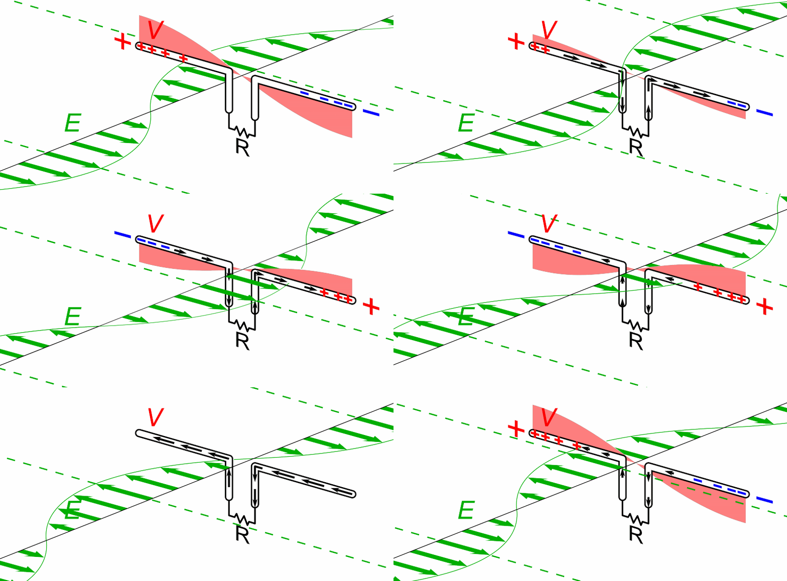
Now an antenna doesn't have to be a wavelength long; in fact they fit the antenna best when the antenna is one half wavelength long, fed at the center. This is going to blow some of your minds, but the current and voltage distribute like this on a half wave long, center-fed antenna, with each side 1/4 wave long. Let's call the voltage positive on the top side (left) and negative on the bottom (right); so current is positive above the line, too.

The "why??" is pretty simple. Remember that power is voltage time current, so if the power is constant, the product can stay the same while the current and voltage can both vary from zero to their maximum along the wires. The current is minimum at the ends because the current has nowhere to go. Electrons can't go past the end of the wire. The voltage is maximum at the ends because the current stops; since I*V is constant and I is getting very small, the voltage gets very big.
Note that the picture is a snapshot of a very short period in time. The voltage is continually changing polarity, end to end, at the frequency of the wave, and so is the current, but the current and voltage being out of phase with each other as pictured (one max while the other is min) doesn't change. There's a good animation in the wikipedia.
By the way: if you want to build a dipole, two quarter wave long wires fed in the middle, a century of experience says to cut the wire to 468/f, where f is the frequency in MHz and it gives you the answer in feet. Antennas interact a lot with their environment, so it's not uncommon to have to tweak those dimensions to get the best antenna, but this ordinarily gets you close enough to start.
Remember how I said that "the size of the antenna has to match the size of the radio waves it's going to handle"? There's some slack in that statement because as you move the frequency away, it can still "mostly fit". This is what's called the bandwidth of the antenna. This drawing shows the wave fitting on the antenna because the peak of current is a half wave. If the frequency gets too far away, the current would go below zero and every cycle would look a little different because the position of where it crosses zero would move around.
In reality, non-resonant antennas are used regularly. Just as Power is voltage times current and constant, let me drag a concept back from AC circuits: impedance. Impedance is an AC resistance which includes the effects of resistance and reactance. Just like DC resistance is defined as Voltage divided by Current (V/I), impedance is V/I with AC measures. Antennas have a defined impedance, like any AC circuit, and you can make an antenna's impedance look better with tuning circuits. Manual and automated tuners are commonplace. They allow you to make a non-resonant antenna more useful.
The half wave dipole is a standard antenna in a few senses. They are used as an element in other antennas, and their performance by themselves is a standard of comparison. The other standard antenna is 1/2 of a half wave dipole, a quarter wave monopole, usually called a quarter wave vertical because half the antenna is replaced with it's "reflection" in a mirror-like ground that it's mounted vertically over. The current and voltage waves look exactly like the half wave dipole.
In particular, cell phones went from having very obvious, external, quarter wave whip style antennas to internally mounted or otherwise hidden antennas, like these:

Tomorrow - deeper into the weeds.
Friday, February 2, 2018
America is NOT A Violent Culture
I'm personally tired of hearing the gun control nuts saying we're an unreasonably violent culture. We are not, as whole. Proof? Look no farther than former USA Gymnastics team doctor Larry Nassar. If any of the fathers of any of those sexually abused girls was as violent as the Demanding Mommies say Americans are, that MoFo would have long ago been dead and buried in an unmarked grave in the woods. He's up to 175 life sentences now. Some time in the last 20 years, one dad who listened to his daughter could have fixed this, and could have saved a lot of girls and their families from a lot of suffering. No one needed to know. The daughter that faced it didn't need to know why the doctor was suddenly replaced.
The dad that made a scene in the courtroom today did it all wrong. While I admire his honesty, first of all, he should have done it years ago (I couldn't find out how long ago his daughters were involved) and second, don't do that with a court full of security unless you're playing "hold me back" and don't intend to do anything.
So please, Shannon, Bloomie, don't tell me we're a violent society. Don't tell me every single time that any modest extension of self defense law, like Utah's move to adopt the nearly 150 year old stand your ground doctrine, or allowing concealed carry reciprocity, is going to result in "blood in the streets" or "gun fights over parking spaces". It has never happened, and it won't ever happen.

The dad that made a scene in the courtroom today did it all wrong. While I admire his honesty, first of all, he should have done it years ago (I couldn't find out how long ago his daughters were involved) and second, don't do that with a court full of security unless you're playing "hold me back" and don't intend to do anything.
So please, Shannon, Bloomie, don't tell me we're a violent society. Don't tell me every single time that any modest extension of self defense law, like Utah's move to adopt the nearly 150 year old stand your ground doctrine, or allowing concealed carry reciprocity, is going to result in "blood in the streets" or "gun fights over parking spaces". It has never happened, and it won't ever happen.

Thursday, February 1, 2018
Best Science Story in A While
Thanks to a link on Watts Up With That, we learn about a bacteria that refines and excretes gold. That's right. It literally absorbs metal-contaminated water and poops gold. (Journal abstract)
 (Micrograph of the bacterium with five small gold nuggets it excreted. Below, a small body of the excreted gold nuggets. Both pics from WUWT)
 I find this fascinating. First, I think of gold as a noble metal that's notoriously hard to get into chemical reactions, at least the first step of dissolving gold and forming a salt or other compound. Yet bacteria are able to perform complex reactions on the gold and (much more reactive) copper. Secondly, I don't know a whole lot about gold deposits, but it makes me wonder if some of the gold that's found today is the result of bacterial pooping over thousands of years.
High concentrations of heavy metals, like copper and gold, are toxic for most living creatures. This is not the case for the bacterium C. metallidurans, which has found a way to extract valuable trace elements from a compound of heavy metals without poisoning itself. One interesting side-effect: the formation of tiny gold nuggets.This bacteria ordinarily lives in soils that are laced with copper and toxic metals. Over time, some minerals break down in the soil and release these heavy metals and hydrogen (acid) into their environment.
“Apart from the toxic heavy metals, living conditions in these soils are not bad. There is enough hydrogen to conserve energy and nearly no competition. If an organism chooses to survive here, it has to find a way to protect itself from these toxic substances,” explains Professor Dietrich H. Nies, a microbiologist at MLU.MLU is Martin Luther University Halle-Wittenberg in Germany. The other co-authors were at the Technical University of Munich (TUM) and the University of Adelaide in Australia. Professor Nies and his Australian counterpart, Professor Frank Reith, concluded that C. metallidurans is able to deposit gold biologically back in 2009 but only now have elucidated how they do it.
Gold enters the bacteria the same way as copper. Copper is a vital trace element for C. metallidurans however it is toxic in large quantities. When the copper and gold particles come into contact with the bacteria, a range of chemical processes occur: Copper, which usually occurs in a form that is difficult to be taken up, is converted to a form that is considerably easier for the bacterium to import and thus is able to reach the interior of the cell. The same also happens to the gold compounds.
When too much copper has accumulated inside the bacteria, it is normally pumped out by the enzyme CupA. “However, when gold compounds are also present, the enzyme is supressed and the toxic copper and gold compounds remain inside the cell. Copper and gold combined are actually more toxic than when they appear on their own,” says Dietrich H. Nies. To solve this problem, the bacteria activate another enzyme – CopA. This enzyme transforms the copper and gold compounds into their originally difficult to absorb forms. “This assures that fewer copper and gold compounds enter the cellular interior. The bacterium is poisoned less and the enzyme that pumps out the copper can dispose of the excess copper unimpeded. Another consequence: the gold compounds that are difficult to absorb transform in the outer area of the cell into harmless gold nuggets only a few nanometres in size,” says Nies.


Wednesday, January 31, 2018
NASA's (and Our) Worst Week in Spaceflight
We're almost at the end of the worst week of NASA history. It's a peculiar coincidence that every accident that took the lives of the crew and destroyed the vehicle took place in the space of one calendar week, although those accidents are separated by decades.
January 27th, was the 51st anniversary of 1967's hellish demise of Apollo 1 and her crew, Gus Grissom, Roger Chaffee and Ed White, during a pad test, not a flight. In that article, Ars Technica interviews key men associated with the mission and provides, for the first time I've seen, the audio of the test. In the early days of the space program, one of the larger than life names we all came to recognize was Chris Kraft, the Capsule Communicator or CapCom who had directed all of the Mercury flights, many of the Gemini missions and was widely recognized for this masterful control.
The next day, January 28, is the anniversary of the Space Shuttle Challenger disaster. Shuttle Challenger was destroyed on January 28, 1986, a mere 73 seconds into mission 51-L as a flaw in the starboard solid rocket booster allowed a secondary flame to burn through supports and cause the external tank to explode. It was the kind of cold day that we haven't had here in some years. It has been reported that it was between 20 and 26 around the area on the morning of the launch and ice had been reported on the launch tower as well as the external tank. O-rings that were used to seal the segments of the stackable solid rocket boosters were too cold to seal. Launch wasn't until nearly noon and it had warmed somewhat, but the shuttle had never been launched at temperatures below 40 before that mission. Richard Feynman famously demonstrated that cold was likely the cause during the televised Rogers Commission meetings, dropping a section of O ring compressed by a C-clamp into his iced water to demonstrate that it had lost its resilience at that temperature.

There's plenty of evidence that the crew of Challenger survived the explosion. The crew cabin was specifically designed to be used as an escape pod, but after most of the design work, NASA decided to drop the other requirements to save weight. The recovered cabin had clear evidence of activity: oxygen bottles being turned on, switches that require a few steps to activate being flipped. It's doubtful they survived the impact with the ocean and some believe they passed out due to hypoxia before that.
Finally, at the end of this worst week, Shuttle Columbia, the oldest surviving shuttle flying as mission STS-107, broke up on re-entry 15 years ago tomorrow, February 1, 2003 scattering wreckage over the central southern tier of the country with most debris along the Texas/Louisiana line. As details emerged about the flight, it turns out that Columbia and everyone on board had been sentenced to death at launch - they just didn't know it. A chunk of foam had broken off the external tank during liftoff and hit the left wing's carbon composite leading edge, punching a hole in it. There was no way a shuttle could reenter without exposing that wing to conditions that would destroy it. They were either going to die on reentry or sit up there and run out of food, water and air. During reentry, hot plasma worked its way into that hole, through the structure of the wing, burning through piece after piece, sensor after sensor, until the wing tore off the shuttle and tore the vehicle apart. Local lore on this one is that the original foam recipe was changed due to environmental regulations, causing them to switch to a foam that didn't adhere to the tank or stand up to abuse as well.
There's film from inside Columbia until the moment the vehicle is ripped apart by the aerodynamic forces. I suspect the forces ripped apart their bodies just as fast.
January 27 to February 1 is 6 days. Not quite a full week.
On a personal note, I remember them all. I was a kid living in Miami when Apollo 1 burned. I was living here and watched Challenger live on satellite TV at work. Instead of going outside to watch it as I always did, I watched it on NASA Select. Mrs. Graybeard was working on the unmanned side on the Cape, next door to the facility that refurbished the SRB's between flights, and was outside watching the launch. It took quite a while for the shock to ease up. I saw those spreading contrails everywhere for a long time. Columbia happened when it was feeling routine again. Mom had fallen and was in the hospital; we were preparing to go down to South Florida to visit and I was watching the TV waiting to hear the double sonic booms shake the house as they always did.
When this blog started, one of my regular reads was Dr. Sanity, a flight surgeon for NASA and board-certified psychiatrist. She was Crew Surgeon for Challenger and has left posted a haunting recollection of the mission although her blog hasn't been updated since 2012. It's still there. I conclude with a quote from that post:
"I have come to see NASA as one of the greatest impediments to the Dream of space exploration; but I have never given up the Dream itself." We're in complete agreement.
January 27th, was the 51st anniversary of 1967's hellish demise of Apollo 1 and her crew, Gus Grissom, Roger Chaffee and Ed White, during a pad test, not a flight. In that article, Ars Technica interviews key men associated with the mission and provides, for the first time I've seen, the audio of the test. In the early days of the space program, one of the larger than life names we all came to recognize was Chris Kraft, the Capsule Communicator or CapCom who had directed all of the Mercury flights, many of the Gemini missions and was widely recognized for this masterful control.
Half a century later, the painful memories remain. “I was on console the day it burned,” he explained, sitting in his second-floor den, just a few miles from the control center that now bears his name at Johnson Space Center.The ARS article is worth your time.
“I heard their screaming voices in the cockpit of the spacecraft,” Kraft recounted. “I heard them scream that they were on fire. I heard them scream get me out of here. And then there was dead silence on the pad. Within minutes we knew they were dead, and we were in deep, serious trouble. Nobody really said anything for 15 minutes, until they got the hatch open. We were sitting there, waiting for them to say what we knew they were going to say.”
....
There was plenty of blame to go around—for North American, for flight control in Houston, for technicians at Cape Canaveral, for Washington DC and its political pressure on the schedule and its increasingly bureaucratic approach to spaceflight. The reality is that the spacecraft was not flyable. It had too many faults. Had the Apollo 1 fire not occurred, it’s likely that additional problems would have delayed the launch.
“Unless the fire had happened, I think it’s very doubtful that we would have ever landed on the Moon,” Kraft said. “And I know damned well we wouldn’t have gotten there during the 1960s. There were just too many things wrong. Too many management problems, too many people problems, and too many hardware problems across the whole program.”
The next day, January 28, is the anniversary of the Space Shuttle Challenger disaster. Shuttle Challenger was destroyed on January 28, 1986, a mere 73 seconds into mission 51-L as a flaw in the starboard solid rocket booster allowed a secondary flame to burn through supports and cause the external tank to explode. It was the kind of cold day that we haven't had here in some years. It has been reported that it was between 20 and 26 around the area on the morning of the launch and ice had been reported on the launch tower as well as the external tank. O-rings that were used to seal the segments of the stackable solid rocket boosters were too cold to seal. Launch wasn't until nearly noon and it had warmed somewhat, but the shuttle had never been launched at temperatures below 40 before that mission. Richard Feynman famously demonstrated that cold was likely the cause during the televised Rogers Commission meetings, dropping a section of O ring compressed by a C-clamp into his iced water to demonstrate that it had lost its resilience at that temperature.

There's plenty of evidence that the crew of Challenger survived the explosion. The crew cabin was specifically designed to be used as an escape pod, but after most of the design work, NASA decided to drop the other requirements to save weight. The recovered cabin had clear evidence of activity: oxygen bottles being turned on, switches that require a few steps to activate being flipped. It's doubtful they survived the impact with the ocean and some believe they passed out due to hypoxia before that.
Finally, at the end of this worst week, Shuttle Columbia, the oldest surviving shuttle flying as mission STS-107, broke up on re-entry 15 years ago tomorrow, February 1, 2003 scattering wreckage over the central southern tier of the country with most debris along the Texas/Louisiana line. As details emerged about the flight, it turns out that Columbia and everyone on board had been sentenced to death at launch - they just didn't know it. A chunk of foam had broken off the external tank during liftoff and hit the left wing's carbon composite leading edge, punching a hole in it. There was no way a shuttle could reenter without exposing that wing to conditions that would destroy it. They were either going to die on reentry or sit up there and run out of food, water and air. During reentry, hot plasma worked its way into that hole, through the structure of the wing, burning through piece after piece, sensor after sensor, until the wing tore off the shuttle and tore the vehicle apart. Local lore on this one is that the original foam recipe was changed due to environmental regulations, causing them to switch to a foam that didn't adhere to the tank or stand up to abuse as well.
There's film from inside Columbia until the moment the vehicle is ripped apart by the aerodynamic forces. I suspect the forces ripped apart their bodies just as fast.
January 27 to February 1 is 6 days. Not quite a full week.
On a personal note, I remember them all. I was a kid living in Miami when Apollo 1 burned. I was living here and watched Challenger live on satellite TV at work. Instead of going outside to watch it as I always did, I watched it on NASA Select. Mrs. Graybeard was working on the unmanned side on the Cape, next door to the facility that refurbished the SRB's between flights, and was outside watching the launch. It took quite a while for the shock to ease up. I saw those spreading contrails everywhere for a long time. Columbia happened when it was feeling routine again. Mom had fallen and was in the hospital; we were preparing to go down to South Florida to visit and I was watching the TV waiting to hear the double sonic booms shake the house as they always did.
When this blog started, one of my regular reads was Dr. Sanity, a flight surgeon for NASA and board-certified psychiatrist. She was Crew Surgeon for Challenger and has left posted a haunting recollection of the mission although her blog hasn't been updated since 2012. It's still there. I conclude with a quote from that post:
I remember the Challenger and her crew frequently and with love. They are a part of me now. All of them represent the best within the American spirit, and always will. Since that day in 1986, I have come to see NASA as one of the greatest impediments to the Dream of space exploration; but I have never given up the Dream itself. Nor have I forgotten any of the pioneers who have died in the service of that Dream. Some day we humans will leave this small planet and joyfully play in all the corners of the cosmos.The failure reports and investigations of all three of these disasters center on the same things: the problems with NASA's way of doing things. Tending to rely on "well, it worked last time" when dealing with dangerous situations, or leaning too much toward, "schedule is king"; gambling that someone else would be the one blamed for delaying a mission. Spaceflight is inherently very risky, so some risk taking is inevitable, but NASA had taken stupid risks too often. People playing Russian Roulette can say, "well, it worked last time", but that doesn't mean playing has reduced their odds of losing.
I eagerly look forward to it.
"I have come to see NASA as one of the greatest impediments to the Dream of space exploration; but I have never given up the Dream itself." We're in complete agreement.
Tuesday, January 30, 2018
It's The SOTU Drinking Game!
The State of the Union Drinking Game is easy to follow; and if you don't want to get wasted on a weeknight, you can just play with something else. Have some candy or whatever you want to substitute.
The scoring is that every time the president says any of the following words you take a drink:
 (a picture I've been running for years - usually in my New Years' Eve post)
The scoring is that every time the president says any of the following words you take a drink:
Infrastructure, "roads and bridges", or airportsInfrastructure doesn't have to be preceded by "crumbling" to count. Now go watch! If the evening news is any indication, I guarantee you'll be drunk by 9:30.

Monday, January 29, 2018
Caught an Out-of-Character Movie Today
Regular readers will know that my taste in movies tends to escapist things like Sci-Fi and comic book movies, not serious films about the human condition. Today we went to see Darkest Hour, the movie about the first days of Winston Churchill's term as Prime Minister of the UK.
Over the years, I've realized that my education in history is lacking, and while I think the movie is historically solid, I'm not enough of a Churchill scholar to know. Larry P. Arnn, president of Hillsdale College and an actual Churchill scholar, though, says it is and it's worth seeing. For my part, I've always been an admirer of Churchill, although in the last 20 years I've come to wonder if I really know the man or just a mythology that percolated around America in the 60s to early 70s; while I had the various history classes I was required to take.
I haven't heard much about it besides recommendations from Rush to see it. All I had really heard was that Gary Oldman did a wonderful job of capturing him and should get a Best Actor Oscar for the movie. What I hadn't heard was about the great supporting cast, including Dame Kristin Scott Thomas as his wife, Clemmie, and Lily James as his secretary Liz Layton.
 (Gary Oldman and Kristin Scott Thomas - studio photo)
This is not a bright and cheery movie. What little humor there is comes from Churchill's quips to other people and one or two witty moments. It depicts Churchill in a politically awful position, given the position just as Europe is falling to Nazi Germany; resented awfully by the man he replaced, Neville Chamberlain, and the man who seemed to think he should have been given the role, Viscount Halifax. Hitler's army is sweeping western Europe, pushing the English army onto the beaches of Dunkirk, while Austria and Holland fall, and France breaking down. His military is telling him they can do nothing to rescue the Army from Dunkirk. He wants to fight but is being told he has no military that can do anything.
I usually rate movies on a 1 to 5 scale, and I give this a 5. The acting was remarkable and the way . He'd choose things like the view out of the window of a limousine to drive home how Churchill was seeing people and things in the street, or aerial views to show the impact of the Nazi bombing in France, or a view of spiraling staircase with people moving every which way to convey how urgently busy everything was. I think it's well worth seeing.
Over the years, I've realized that my education in history is lacking, and while I think the movie is historically solid, I'm not enough of a Churchill scholar to know. Larry P. Arnn, president of Hillsdale College and an actual Churchill scholar, though, says it is and it's worth seeing. For my part, I've always been an admirer of Churchill, although in the last 20 years I've come to wonder if I really know the man or just a mythology that percolated around America in the 60s to early 70s; while I had the various history classes I was required to take.
I haven't heard much about it besides recommendations from Rush to see it. All I had really heard was that Gary Oldman did a wonderful job of capturing him and should get a Best Actor Oscar for the movie. What I hadn't heard was about the great supporting cast, including Dame Kristin Scott Thomas as his wife, Clemmie, and Lily James as his secretary Liz Layton.

This is not a bright and cheery movie. What little humor there is comes from Churchill's quips to other people and one or two witty moments. It depicts Churchill in a politically awful position, given the position just as Europe is falling to Nazi Germany; resented awfully by the man he replaced, Neville Chamberlain, and the man who seemed to think he should have been given the role, Viscount Halifax. Hitler's army is sweeping western Europe, pushing the English army onto the beaches of Dunkirk, while Austria and Holland fall, and France breaking down. His military is telling him they can do nothing to rescue the Army from Dunkirk. He wants to fight but is being told he has no military that can do anything.
I usually rate movies on a 1 to 5 scale, and I give this a 5. The acting was remarkable and the way . He'd choose things like the view out of the window of a limousine to drive home how Churchill was seeing people and things in the street, or aerial views to show the impact of the Nazi bombing in France, or a view of spiraling staircase with people moving every which way to convey how urgently busy everything was. I think it's well worth seeing.
Sunday, January 28, 2018
A Little Weekend Update
Let me bring you up to date on the various projects and stories I've talked about.
On the oscilloscope: the 5000 PIV diodes arrived yesterday and I wasted no time getting them into the circuit. No joy. I ran the scope on the variac box at 100V, but it has a "line voltage too low" light that was on. I bumped up the line voltage until that went out. The problem is that there appears to be no horizontal sweep of any kind, and the only time I see anything is if I press the beam finder button. If I put a probe on the builtin calibrator (a 300mV pk-pk 1kHz square wave) and press beam finder, it spreads out to look like the correct voltage only without a sweep.
 These are the parts I changed. The circuitry surrounds the horizontal sweep voltage and the high voltage, but it seems to involve lower voltage circuitry as well (I never see the sync light come on when I'm probing the calibrator). I found test points for all the lower voltages in the unit (< 1000VDC) and all of those are good. Troubleshooting will continue, although to really troubleshoot an oscilloscope requires another oscilloscope.
BTW, I got 10 of those diodes expecting to blow them as soon as I replaced them, and go through a few pairs before the thing worked. The replacement diodes are still good.
The miniature K9AY loop antenna has turned out to work "pretty well". I have no comparison of a full-sized version, so I can't evaluate it that way, but I have a few contacts using it and measured some parameters like the front to back null as best I can. On 10.1 MHz (30m), its targeted band, signals may be just a little weaker than my reference antenna, but it has about a 20 dB front to back ratio, which might be helpful. Signals seem lower on other bands, but Signal to Noise Ratio is sometimes better; it probably depends on things like the exact angle of arrival, the specific noise or interference source I'm having trouble with, and other parameters that are hard to quantify. Slightly surprisingly, it seems to work fairly well on 3.5 MHz (80m), which is the target band for the full-sized loop.
The variac box has turned out to be really helpful and something I should have done before. I've powered on all of my old vacuum tube gear (except an R-390A that I use several times a year) going through a protocol of leaving it on 90V, then 100, 110V each for an hour and finally the wall 120V. All of the old equipment is behaving fine. Nothing smoked.
It took me a while to find a schematic editor that I like to produce a drawing for the variac box. TinyCAD, totally freeware. I have PCB123 for small PWBs if I design something that needs a board, but for this application I wanted something more like the plastic stencils we used to use in the years BC (Before CAD); I have no need for PWB component footprints for something wired point-to-point using duplex AC outlets from the hardware store.
 I upgraded the project guitar, giving it nicer tuning machines. The fit, finish and functional smoothness are noticeably better than the $8 eBay specials I put on it first, but I honestly had no idea it would even survive having strings put on it. I did a complete setup to the action to make it easier to play, and more like my best acoustic. The work included setting the neck bow, leveling the frets, with my fret rocker and an 8" mill file, then adjusting the string heights with my string height gauge with nut slotting files at the nut and lowering saddle height at the other end.
The other things that I've been dumping vast amounts of time into are probably too esoteric even for this crowd (I'm guessing a handful of you are intimately familiar with the Smith Chart, for example), and choosing the next project for the metal shop. I haven't actually chosen that, but I'm getting closer.
And that's some of what's going on that I don't always write about!
On the oscilloscope: the 5000 PIV diodes arrived yesterday and I wasted no time getting them into the circuit. No joy. I ran the scope on the variac box at 100V, but it has a "line voltage too low" light that was on. I bumped up the line voltage until that went out. The problem is that there appears to be no horizontal sweep of any kind, and the only time I see anything is if I press the beam finder button. If I put a probe on the builtin calibrator (a 300mV pk-pk 1kHz square wave) and press beam finder, it spreads out to look like the correct voltage only without a sweep.

BTW, I got 10 of those diodes expecting to blow them as soon as I replaced them, and go through a few pairs before the thing worked. The replacement diodes are still good.
The miniature K9AY loop antenna has turned out to work "pretty well". I have no comparison of a full-sized version, so I can't evaluate it that way, but I have a few contacts using it and measured some parameters like the front to back null as best I can. On 10.1 MHz (30m), its targeted band, signals may be just a little weaker than my reference antenna, but it has about a 20 dB front to back ratio, which might be helpful. Signals seem lower on other bands, but Signal to Noise Ratio is sometimes better; it probably depends on things like the exact angle of arrival, the specific noise or interference source I'm having trouble with, and other parameters that are hard to quantify. Slightly surprisingly, it seems to work fairly well on 3.5 MHz (80m), which is the target band for the full-sized loop.
The variac box has turned out to be really helpful and something I should have done before. I've powered on all of my old vacuum tube gear (except an R-390A that I use several times a year) going through a protocol of leaving it on 90V, then 100, 110V each for an hour and finally the wall 120V. All of the old equipment is behaving fine. Nothing smoked.
It took me a while to find a schematic editor that I like to produce a drawing for the variac box. TinyCAD, totally freeware. I have PCB123 for small PWBs if I design something that needs a board, but for this application I wanted something more like the plastic stencils we used to use in the years BC (Before CAD); I have no need for PWB component footprints for something wired point-to-point using duplex AC outlets from the hardware store.

The other things that I've been dumping vast amounts of time into are probably too esoteric even for this crowd (I'm guessing a handful of you are intimately familiar with the Smith Chart, for example), and choosing the next project for the metal shop. I haven't actually chosen that, but I'm getting closer.
And that's some of what's going on that I don't always write about!
Any Fellow Bloggers Having Problems with Blogger Itself?
Quick question for any bloggers who drop by: is anybody else having trouble with blogger? Yesterday, I tried to load the "new post" page several times during the day and it never loaded. I'd let it sit for up to 10 minutes, and did that for over half an hour with it never opening.
Likewise the "design" page that allows me to edit the layout, and so on.
Today, they're loading but it just took at least a full minute for this page to load.
Likewise the "design" page that allows me to edit the layout, and so on.
Today, they're loading but it just took at least a full minute for this page to load.
Friday, January 26, 2018
Endless Chances to Show Nobody Knows Everything
More like endless chances to show I personally don't know sh*t. Especially painful in my field of electronics.
Short background. Since about 1997 or '98, I had a TI-86 graphing calculator at my hand, primarily because of its complex number support and my field uses a lot of complex numbers. I bought it when I had problems with the calculator I used before that for 10 or 15 years, a TI-85. I had a half dozen or so programs in it which I had written to do everyday job-related tasks for me. When I retired, it was mine, so it came home with me and it stayed by my side at the computer.
A week ago, I knocked it off its temporary perch near my left knee and it fell a foot to the hard tile floor. As it has done at least a dozen times before. This time it didn't turn on.
Bear in mind, the calculator was in perfect condition; the batteries were relatively fresh, and I had no reason to think anything happened other than a fall.
I took it apart and looked for something loose, but that's like opening the hood when your car dies on the road and looking for the spark plug fairy; that magical obvious thing you see like a loose spark plug wire that you move and your car goes back to running perfectly. No magic calculator fairies to be found.
So I went on eBay, found one that looked to be in good shape, and ordered a replacement. Under $25 with shipping. That was Friday the 20th. It arrived yesterday. I transfer the batteries from the old one into the new one and ... nothing. Won't power on.
Remember I said the batteries were fine? The '86 has a built-in battery check of sorts; the display dims as the battery weakens. You press a key combination and it gets darker or lighter. There are at least 8 levels it displays with 2 or 3 sublevels for each of those 8. I was on level 3. At some point, the calculator starts issuing warnings that the batteries are weak and that starts at level 6 or 7. No, the batteries behaved fine before the fall. So I grabbed four fresh new AAA batteries out of storage and it turned on. Now I looked suspiciously at my original; the one I replaced. Nah, it couldn't be.
It was. I now have two fully functional TI-86 calculators, although my programs got wiped.

I have never seen batteries fail by being dropped, but one of them did.
Short background. Since about 1997 or '98, I had a TI-86 graphing calculator at my hand, primarily because of its complex number support and my field uses a lot of complex numbers. I bought it when I had problems with the calculator I used before that for 10 or 15 years, a TI-85. I had a half dozen or so programs in it which I had written to do everyday job-related tasks for me. When I retired, it was mine, so it came home with me and it stayed by my side at the computer.
A week ago, I knocked it off its temporary perch near my left knee and it fell a foot to the hard tile floor. As it has done at least a dozen times before. This time it didn't turn on.
Bear in mind, the calculator was in perfect condition; the batteries were relatively fresh, and I had no reason to think anything happened other than a fall.
I took it apart and looked for something loose, but that's like opening the hood when your car dies on the road and looking for the spark plug fairy; that magical obvious thing you see like a loose spark plug wire that you move and your car goes back to running perfectly. No magic calculator fairies to be found.
So I went on eBay, found one that looked to be in good shape, and ordered a replacement. Under $25 with shipping. That was Friday the 20th. It arrived yesterday. I transfer the batteries from the old one into the new one and ... nothing. Won't power on.
Remember I said the batteries were fine? The '86 has a built-in battery check of sorts; the display dims as the battery weakens. You press a key combination and it gets darker or lighter. There are at least 8 levels it displays with 2 or 3 sublevels for each of those 8. I was on level 3. At some point, the calculator starts issuing warnings that the batteries are weak and that starts at level 6 or 7. No, the batteries behaved fine before the fall. So I grabbed four fresh new AAA batteries out of storage and it turned on. Now I looked suspiciously at my original; the one I replaced. Nah, it couldn't be.
It was. I now have two fully functional TI-86 calculators, although my programs got wiped.

I have never seen batteries fail by being dropped, but one of them did.
Wednesday, January 24, 2018
I Get a Bad Feeling About This
The Consumer Electronics Show, CES, took place two weeks ago and I have gotten virtually no feedback on it. I don't know what's up with that, but maybe the newsletters and daily emails I get from the few trade magazines I keep up with now think they're too specialized to do a show like CES. (The best coverage I got was a few years ago when one of them sent a reporter to the show for the full week and she did a full update every day).
The one thing I do know of doesn't fill me with ... positive, warm fuzzy feelings. It's about wireless charging of every battery-powered device in the room. According to the Electronic Design newsletter, Powercast and Energous demonstrated systems at the show. In broad brush terms the systems are the same, they use a radio frequency (RF) signal and transmit the power to the wireless device which then takes the received power and turns it into DC to recharge the battery. Energous shows this conceptual picture of what they call their WattUp system.
 (The WattUp system. What happens when the cat gets in front of the transmitter?)
Let me be clear: this is not the wireless charging that works by placing your phone on a charging mat or charging station. As Powercast says:
Powercast has an FAQ that addresses some of these realities. They say they're targeting low capacity batteries, like smart watches, and deliver small amounts of power:
Energous' website has a product concept video with the mandatorily-attractive millennial couple enjoying wireless charging of their devices, but they also feature a page talking about having three tiers of product: far field (which I've just dissected), mid field and near field. If they can meet the power safety limits, perhaps by designing the system to sense the load and shutdown if a hand gets in the way, I can see that near field charging might be more workable.
Systems that a battery operated car would park over and that would charge a multi-hundred kW car battery are left as blog fodder for another day.
 Powercast
graphic, from Electronic Design. Note the third and fourth line: 3 W EIRP
(Effective Isotropic Radiated Power*) and Charges up to
30 devices. The source article says it's a 6 dB gain antenna, so the transmit power is really 750mW and each device can see no more than 750/30 or 25 mW and the low gain implies the antenna is radiating a large sector in front of the box, so each square centimeter is going to see less than that. It seems to be in line with the 1 mW/sq.cm. rule.
Powercast
graphic, from Electronic Design. Note the third and fourth line: 3 W EIRP
(Effective Isotropic Radiated Power*) and Charges up to
30 devices. The source article says it's a 6 dB gain antenna, so the transmit power is really 750mW and each device can see no more than 750/30 or 25 mW and the low gain implies the antenna is radiating a large sector in front of the box, so each square centimeter is going to see less than that. It seems to be in line with the 1 mW/sq.cm. rule.
The problem I haven't mentioned and the reason I get a bad feeling about this is because there's a segment of the population that believes that being immersed in radio fields is dangerous to their health. Can you imagine those people wanting to accept this into their world? How about their workplace?
(* - Effective Isotropic Radiated Power is a combination of the transmit power increased by the antenna gain, which comes from forcing the radio waves in one preferred direction vs. other directions. Gain compared to a theoretical isotropic antenna that radiates equally well in all directions is used instead of gain compared to a real antenna like a dipole (dBd) because it makes bigger numbers and bigger numbers sell better. Attempts by antenna makers to define the "gain with respect to a wet banana peel (dBbp)", which gave really big numbers, were never successful because nobody could agree on a standard reference banana peel.)
The one thing I do know of doesn't fill me with ... positive, warm fuzzy feelings. It's about wireless charging of every battery-powered device in the room. According to the Electronic Design newsletter, Powercast and Energous demonstrated systems at the show. In broad brush terms the systems are the same, they use a radio frequency (RF) signal and transmit the power to the wireless device which then takes the received power and turns it into DC to recharge the battery. Energous shows this conceptual picture of what they call their WattUp system.

Let me be clear: this is not the wireless charging that works by placing your phone on a charging mat or charging station. As Powercast says:
Behaving like Wi-Fi where enabled devices automatically charge when within range of a transmitter, Powercast’s contactless charging technology provides over-the-air power at a distance to multiple devices – no wires, charging mats or direct line of sight needed. A transmitter sends RF energy to Powercast’s Powerharvester® receiver embedded in a device, which converts it to direct current (DC) to directly power that device or recharge its batteries. Operating across a wide RF power (as low as -17 dBm) and frequency (10MHz to 6GHz) range, the Powerharvester receivers are designed to convert RF to DC with up to 80 percent efficiency.Let's dissect that for just a moment. For the simplest possible scenario, and skipping some relevant details, we're talking about a tiny amount of power there. 1 dBm is a power level that is 1dB (10*log of the power ratio) stronger than 1 mW. -17 dBm works out 20 microwatts; 20 millionths of a watt (converter here, if you'd like). The familiar USB chargers are typically 5 or 10 Watts. If your device charged in an hour on that (does any phone?) it would take 500,000 times longer (10/.000020), turning that one hour charge into 57 years. And this is going to sell? Reality is that any battery will die before that recharges it, so how is that even reasonable? And what if there are multiple devices to spread that power over?
Powercast has an FAQ that addresses some of these realities. They say they're targeting low capacity batteries, like smart watches, and deliver small amounts of power:
Available energy after conversion in the low milliwatt and microwatt range should be expected.There's another way to think about this that might help set a limit. What is the maximum power that could be used to charge a device? That's actually set by radiation safety limits mandated by the Federal Communications Commission in the US and for systems to which the general population is exposed, the FCC limits power in this range are defined in terms of milliwatts per square centimeter. The limit at their upper frequency (the 5 GHz WiFi band) is 1 mW/sq.cm. while at the lowest frequency they mention (10 MHz), the power limit is 1.8 mW (FCC OET56 4th edition, 1999, appears to be the latest - pdf warning). Again, skipping over some details, let's assume they can deliver all that 1 thousandth of a watt to one device, and that they can get 1mW/in a 1 sq.cm. antenna. Compared to the "mythical 1 hour recharge at 20 Watts", this one would take over 20,000 hours to deliver the same amount of charge. That's still over two years of charging 24/7/365. And I'm ignoring the 80% efficiency claim, which makes that charge time longer.
Energous' website has a product concept video with the mandatorily-attractive millennial couple enjoying wireless charging of their devices, but they also feature a page talking about having three tiers of product: far field (which I've just dissected), mid field and near field. If they can meet the power safety limits, perhaps by designing the system to sense the load and shutdown if a hand gets in the way, I can see that near field charging might be more workable.
Systems that a battery operated car would park over and that would charge a multi-hundred kW car battery are left as blog fodder for another day.

The problem I haven't mentioned and the reason I get a bad feeling about this is because there's a segment of the population that believes that being immersed in radio fields is dangerous to their health. Can you imagine those people wanting to accept this into their world? How about their workplace?
(* - Effective Isotropic Radiated Power is a combination of the transmit power increased by the antenna gain, which comes from forcing the radio waves in one preferred direction vs. other directions. Gain compared to a theoretical isotropic antenna that radiates equally well in all directions is used instead of gain compared to a real antenna like a dipole (dBd) because it makes bigger numbers and bigger numbers sell better. Attempts by antenna makers to define the "gain with respect to a wet banana peel (dBbp)", which gave really big numbers, were never successful because nobody could agree on a standard reference banana peel.)
Tuesday, January 23, 2018
Time Out
I'm coming down with something, and I'm just hoping it's not this year's flu/creeping crud. As a result blogging will slow down for a day or two (I guess).
Woke up at 5 AM with stomach pains and some nausea. Eventually got back to sleep at 7:30 for a couple of hours. It has been stalking me all day long. Low grade fever, about 100.4. I actually took a nap from about 3-5 this afternoon. That is so far from normal for me that it's a warning sign.
So... cartoon!

Woke up at 5 AM with stomach pains and some nausea. Eventually got back to sleep at 7:30 for a couple of hours. It has been stalking me all day long. Low grade fever, about 100.4. I actually took a nap from about 3-5 this afternoon. That is so far from normal for me that it's a warning sign.
So... cartoon!

Monday, January 22, 2018
So The Dreaded Government Shutdown Was a Three Day Weekend
As the news is saying, (to quote Poultry Heist) "they're ba-ack!" Paid, of course. Everyone always gets paid for the missed day, at least in the history of gubmint shutdowns.
My condolences to those of you who got the three day weekend and are going back to work tomorrow.
Turns out the shutdown did have an effect. A planned static engine test for the SpaceX Falcon Heavy that was on Saturday was cancelled and the shutdown was cited as the reason. The test will probably happen this week. They had said the launch was targeted to be by the end of the month if the tests went well, so the delay probably pushes it into early February. Note of course that these tests are not empty formalities without risk. SpaceX lost a payload, rocket and most of a launch complex doing such a test in September of '16. And that rocket was 1/3 the power of the Heavy.

So whatever will we do? We're in the awkward gap between the end of the shutdown and the news coming out of SHOT show.
My condolences to those of you who got the three day weekend and are going back to work tomorrow.
Turns out the shutdown did have an effect. A planned static engine test for the SpaceX Falcon Heavy that was on Saturday was cancelled and the shutdown was cited as the reason. The test will probably happen this week. They had said the launch was targeted to be by the end of the month if the tests went well, so the delay probably pushes it into early February. Note of course that these tests are not empty formalities without risk. SpaceX lost a payload, rocket and most of a launch complex doing such a test in September of '16. And that rocket was 1/3 the power of the Heavy.

So whatever will we do? We're in the awkward gap between the end of the shutdown and the news coming out of SHOT show.
Sunday, January 21, 2018
Record Deregulation in 2017
During the final days of the campaign in '16, candidate Trump said he'd ask department heads to remove regulations at 2:1, that is, two removed for every one added. As the spreader of Tales From the Over Regulated State, I was very happy to hear that. Instead, Trump revealed in December that they had achieved 22:1 regulations removed to added, which is really change I can believe in.
The Competitive Enterprise Institute noted by the end of last year that the Federal Register for the year had the fewest pages since 1993 - a quarter of a century.
 Wayne Crews of the CEI adds:
 The Forbes article on deregulation opens with this photo opportunity shot of Trump showing the regulatory growth since the 1960s and promising to return federal regulations to 1960s levels. Without dismantling yuge swaths of the Federal hydra, that's impossible. Most of those regulations come from agencies that didn't even exist in the '60s; e.g., no EPA, no Department of Energy, no OSHA, no Department of Homeland Security, no Consumer Product
Safety Commission and no Consumer Financial Protection Bureau. To name a few obvious offenders.
The Forbes article on deregulation opens with this photo opportunity shot of Trump showing the regulatory growth since the 1960s and promising to return federal regulations to 1960s levels. Without dismantling yuge swaths of the Federal hydra, that's impossible. Most of those regulations come from agencies that didn't even exist in the '60s; e.g., no EPA, no Department of Energy, no OSHA, no Department of Homeland Security, no Consumer Product
Safety Commission and no Consumer Financial Protection Bureau. To name a few obvious offenders.
 The consensus is that it isn't within the president's powers to reduce the pile on the right to the size of the pile on the left. But the consensus was also that Trump had no chance of being elected president. A guy can dream, though, can't he?
The Competitive Enterprise Institute noted by the end of last year that the Federal Register for the year had the fewest pages since 1993 - a quarter of a century.
The calendar year concluded with 61,950 pages in the Federal Register… This is the lowest count since 1993’s 61,166 pages. …A year ago, Obama set the all-time Federal Register page record with 95,894 pages. Trump’s Federal Register is a 35 percent drop from Obama’s record… After the National Archives processes all the blank pages and skips in the 2017 Federal Register, Trump’s final count will ultimately be even lower. [Bold added - SiG]Consider this graphic excerpted from the CEI

Of course, the Federal Register may be a poor guide for regulation, but Washington doesn't go out of its way to honestly measure itself and disclose regulatory impact.Director of the George Washington University Regulatory Studies Center Susan Dudely writes for Forbes on the differences Trump is making.
The “problem” of assessing magnitude is even worse this year, because many of Trump’s “rules” are rules written to get rid of rules.
The pace of new regulation has visibly slowed in the Trump administration. A search of OMB’s database reveals that, between January 21 and December 20, 2017, the Office of Information and Regulatory Affairs concluded review of 21 “economically significant” regulations—those with impacts (costs or benefits) expected to be $100 million or more in a year. As the chart below shows, that is dramatically fewer rules than previous presidents have issued in their first years. This same database shows that Presidents G.H.W. Bush, Clinton, and G.W. Bush each issued 39 or 40 in their first years. President Obama issued 52 and even Reagan (considered the last deregulatory president) issued 36 economically significant final rules during his first year in office.


Subscribe to:
Posts (Atom)