Over the course of the last few weeks, I’ve been working on and planning a project to improve my ham radio station. It involves a change to my directional antenna for the six meter ham band. Somewhere else in the same time interval, I saw a reference to directional antennas for emergency and SHTF communications. The combination gave me the idea this might be a worthwhile thing to talk about.
A word about how I’m going to go about this. In an effort to reduce the amount of nitpicky and often extraneous information that could go into a piece like this, I’m going to make some sweeping generalizations without a lot of time to justify them. After all, the ARRL Antenna Book is over a thousand pages, and is just one of the books they sell.
Let me start here. What I’m going to write about applies everywhere in radio. It doesn’t matter if you’re trying to operate low power (QRP) or high (QRO), portable or fixed station, low frequency to microwaves, beginner to very experienced. The antennas will sometimes look very different like a microwave dish versus a VLF vertical, but the concepts are valid everywhere.
Furthermore, let me start with a statement that might surprise a lot of you. Let’s say you got a Christmas bonus or came across an unexpected chunk of money and want to improve your station. Needless to say, the same goes if you’re saving up to improve your station. If you have a reasonably good radio, not even a top-end, extreme-featured radio, just reasonably good, chances are that the best thing you could do to improve your station is improve your antenna system. If you have that reasonably good radio, an improvement in your antenna system is going to help you more than a power amplifier for the simple reason that the antenna will work on both transmit and receive while the power amplifier just helps on the transmit side. Probably the oldest cliché in Ham Radio is “you can’t work ‘em if you can’t hear ‘em.”
Antenna Gain
What directive antennas do for you that makes them the best thing you can do to improve your station is to provide gain. In radio speak, gain is to make signals bigger. It’s what amplifiers do. Unlike amplifiers, though, antennas are passive devices – you don’t supply power to them so they can’t amplify (remember the first law of physics: you don’t get something for nothing?). So how do they create bigger (louder) signals? Think of squeezing a balloon; as you squeeze the balloon you make part of the balloon bigger as you squeeze the air out of the rest of it and the parts of the balloon you are squeezing get smaller.
As always (first law again!) there are good aspects and bad aspects of this. The good side is really good. Let’s say you squeeze the balloon and get four times more power going in the direction the antenna is pointed (6dB gain – which isn’t terribly hard to get). You haven’t put any more watts out, the power at the antenna is exactly what it was before, but you’ve made your signal at the other guy’s receiver a full S-unit stronger which made your signal much easier to understand. Furthermore, you’ve done that by reducing the amount of power you put in undesired directions, reducing the amount you might interfere with others. Even better, that same forward gain reduces your receiver sensitivity in other directions, making it easier for you to hear the desired station if interference isn’t exactly in the same direction as the station you’re working. In antenna design, they often talk about front to back ratio and even small directional antennas can put 20 dB less power out the back than the front (1/100 the power). It’s not always specified, but front to side ratio can be more important than front to back in populated places like much of the US. It’s not uncommon to see front to side ratios of 30 dB (1/1000 the power) and more.
The bad aspect for many hams is that you need to be able to reposition the antenna to get it to point exactly where you want. In most cases, that’s done with an antenna rotator that has to be wired into place outdoors and controlled from inside the station. There are antenna systems where rotation is done entirely electrically, too. If you need to communicate with other stations in opposite directions, this can be a problem. In some extreme situations, you might want to switch between two antennas pointed in both directions. Most of the time, the communications can be arranged to keep from needing that. The only disadvantage to you is that if you’re trying for stations at very different headings, you tend to need to contact one, then rotate the antenna and try for the other.
That rarely seems to be a major hardship.
How Do I Get Me Some?
How do you get antenna gain? The simplest way to look at it is that you need to put more metal in the air, but I hope you understand that if you just put up randomly sized hunks of metal in equally randomly chosen places that doesn’t count. There are many established antenna designs to get gain, and you need to buy or build one of them.
In broad-brush overview, there are two main types of antennas; those whose performance is determined by being portions of a wavelength, that is, made of quarter, half or full wave elements and those whose performance is largely determined by angular relationships between the elements which tend to be broader bandwidth than the first kind. Since angles of electrical length can be expressed as physical lengths, it can be easy to lump them together.
The most common examples of the first kind are commonly called beam antennas, most are actually Yagi arrays (and more properly Yagi-Uda after both original inventors). Just behind those in popularity are quad antennas; these are based on four sided, full wavelength loops, most often of wire. There are also arrays of vertical antennas; most commonly four verticals forming a square array. Quad and Yagi arrays look like this:
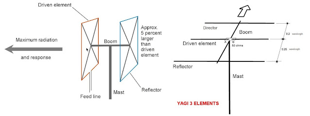
The one on the left is a two element quad (full wave loops) while the one on the right is a three element Yagi (half wave elements). A two element quad is generally considered equivalent to a three element Yagi based on real measurements. You can justify that by saying “there’s more metal in the air so more gain.” Again, these are classes of antennas; both kinds are available with different numbers of elements. There have been antennas that were a hybrid, with a quad driven element and sometimes a quad reflector and then Yagi directors. There are quads made into hexagons, quads with two wavelength elements and other variations.
While designing for antenna gain is an art form, the general trends are that more elements and longer booms give more gain. It’s a game with diminishing returns. Each additional half wave element (always a director) gives improvement but think of it as 10 * log(new number/old number). That is, going from three to four elements yields 10*log(4/3) or 1.25 dB but going from 10 to 11 elements gives 0.4 dB.
There comes a point when if you need twice the gain, the way to get there is by adding a second antenna with the same number of elements. “Stacked Yagis” (two identical antennas), four antennas and even two arrays of four antennas are used where high antenna gain is required, like communicating by bouncing signals off the moon.
The antennas whose performance is largely determined by angular relationships are very common and if you’re old enough to know about outdoor TV antennas, you’ve seen them all your life. The descriptive name is Log Periodic Dipole Arrays, or LPDA antennas.
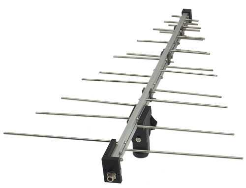
This may look like a tapered Yagi at first glance, but look at the dipoles again. The two halves alternate between two booms that are insulated from each other. In other words, you see the connector on the bottom front, a signal driving that “dipole” drives the right side, travels down the entire length of the bottom boom to the far end, moves up to the top boom and travels all the way back to just above the connector.
While a Yagi is typically good for just one amateur band (ignoring antennas that have traps to allow use on multiple bands), LPDAs are common with frequency ranges from 2:1 to 10:1. My HF antenna for 14 to 30 MHz is an LPDA (and I’ve used it successfully on 50.1 MHz), I’ve seen LPDAs for 50 to 500 MHz. (My HF antenna is a Tennadyne T6) The trade is that generally no more than two or three dipoles are active on any frequency, so while they cover a broad band of frequencies, they’re not the choice for a high gain antenna. We used to say, “they’re an antenna that works poorly over a wide range of frequencies.” (And, yes I just said I'm currently using one for HF and another for VHF)
Mounting the antenna, towers and such are not really part of this discussion. All horizontal antennas, whether a simple random length wire, a dipole, or a humongous Yagi for 20 meters work better when mounted over ½ wavelength above ground and in the clear. For 20 meters, a half wave is obviously 10 meters, about 33 feet. That’s a very different support problem than a yagi for 40, 80 or 160meters. For those bands, I think vertical antennas are the best choice for the ham without 40 acres and a big budget. Note that means that a 2 meter antenna can work fine at just over 3 feet over ground. From the feedpoint impedance view, that’s completely correct. It will still work better if it’s higher because of that part about being “in the clear.”
In my case, the work has been lining up a replacement for my 6m antenna, a no-longer manufactured five element, dedicated, six-foot long 6m LPDA with a five element Yagi. My antenna lists its gain as 7.2 dBi in free space. The replacement I’ve picked out is twice as long, and has 10.2 dBi gain in free space. The limiting factor that got me to stop at five elements instead of six (slightly more gain) is the resulting boom length and being able to take down the antenna for a storm. What the existing 6m LPDA offers that my new antenna won't is it operates acceptably on 2m and even loads on 70cm (432 MHz SSB or CW), but it's not a particularly good antenna on either of those two bands.
Thank you; more than crystal clear
ReplyDeleteFor those bands, I think vertical antennas are the best choice for the ham without 40 acres and a big budget.
ReplyDeleteWhen I was in in middle school in Gainesville, I briefly put up a cubical quad in my suburban back yard about 15 feet on a side for a radio astronomy science project.
15 feet on a side? I would expect to be for about 20 or 21 MHz. Isn't that where we can hear Jupiter?
DeleteAnyway... my first "real" antenna with gain was a quad for 20, 15 and 10 meters back in the '70s. This was before the WARC bands at 17 and 12 meters but they would have been easy to add. It was from another small company that's now gone and called a GEM quad. There are two main types of quads. There's the spider design where the spacing stays proportional to a wavelength by mounting the arms at an angle so lower frequencies are farther apart than higher frequencies, and the the kind that has planar arrangements of the wire loops so that the electrical spacing is different on every band. The GEM quad was a spider design.
It was such an incredible step up from wire antennas near the ground level it was amazing. The only real drawback to the quad was that it wouldn't allow what I had now, which is two antennas stacked vertically; a smaller VHF antenna above a larger HF antenna.
I remember GEM Quads. I've never used a Quad before, only Yagis and verticals.
ReplyDeleteYour quote about the LPDAs reminds of a similar quote about the verticals I'm fond of: They Radiate Equally Poorly In All Directions.....
Have you tried a log periodic or (if you have a lot of land) a rhombic?
ReplyDelete