The initial article in this couple of episodes on power supplies focused on low power supplies and especially the 78XX series of regulators. There are actually many similar parts and series of parts that provide three pin regulators. Given how versatile and useful they are, I want to explore a use I have for one. I've based it on a part I'm familiar with and have in my junk box (ham speak for a box of parts you have from various sources for future projects), the LM323, a 5V 3A regulator.
The electronic ignition I bought for my Webster engine required a power supply not to exceed 5V. The company that sells the engine sells a 5V supply to run the system, but in my urge to get going as fast as possible, I put together a system of 3 AA cells in series. When the cells are new, it puts out in the vicinity of 4.8V but it falls to 4.5V quickly. The instructions with the ignition module says it works best at 5.0 to 5.5V, but dies quickly over that. Four AA alkalines will kill the module. Three will get it to work, but not as well as it could. You might recall this picture of the ignition module (right) and battery pack with one battery replaced by a jumper.

After throwing out several sets of these AA batteries I decided to upgrade everything. I could replace the AA alkaline batteries with the 18650 rechargeable lithium batteries I bought a couple of years ago. Those are over 8V fully charged and run down to the 6.5V dropout voltage of the regulator. The circuit is drop dead simple.

The application circuit is assuming that this is on the output of a rectifier and filter combination; I'm not using that so I didn't put that 1uF solid tantalum capacitor there. I put a 0.1uF ceramic capacitor on the input and a 0.22 uF solid tantalum on the output side. (Note that the LM123 pictured is their name for the same part tested to full military spec temperature ranges. There's an LM223 that is for the extended industrial temperature range and the LM323 is for the commercial temperature ranges)
The regulator is in a large, chassis mounted case called a TO-3 (Transistor Outline), and a dimensioned drawing of the package is in the datasheet for the LM323 on that TI page linked above. I used that to develop a routine for drilling the holes for the TO-3 that I can keep in my CNC library. Then I set to the task of creating a model in CAD to space the parts from each other. The LM323 is in blue, with batteries on the right and ignition module on the left. I didn't model the other parts - and the regulator is mounted on the far side of this channel, with it's input and output pins protruding through the drilled out holes.

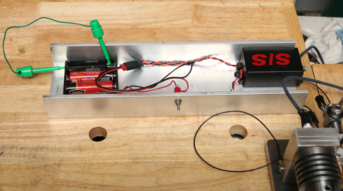
The regulator circuit is built without the electronic ignition module, and checked to verify it puts out 5V properly, which it does. Tomorrow, I'll add the ignition module and I want to try to run my Webster with it. The engine has been sitting for a month or six weeks with no attempts to start it.
The catch is I don't really know what the requirements are for that 5V supply. It might not work and just need a bigger capacitor on the output to supply current surges the module may require.
The aluminum channel you're looking down into above will have printed plastic feet on the far side to keep the regulator case off the bench.
The electronic ignition I bought for my Webster engine required a power supply not to exceed 5V. The company that sells the engine sells a 5V supply to run the system, but in my urge to get going as fast as possible, I put together a system of 3 AA cells in series. When the cells are new, it puts out in the vicinity of 4.8V but it falls to 4.5V quickly. The instructions with the ignition module says it works best at 5.0 to 5.5V, but dies quickly over that. Four AA alkalines will kill the module. Three will get it to work, but not as well as it could. You might recall this picture of the ignition module (right) and battery pack with one battery replaced by a jumper.
After throwing out several sets of these AA batteries I decided to upgrade everything. I could replace the AA alkaline batteries with the 18650 rechargeable lithium batteries I bought a couple of years ago. Those are over 8V fully charged and run down to the 6.5V dropout voltage of the regulator. The circuit is drop dead simple.

The application circuit is assuming that this is on the output of a rectifier and filter combination; I'm not using that so I didn't put that 1uF solid tantalum capacitor there. I put a 0.1uF ceramic capacitor on the input and a 0.22 uF solid tantalum on the output side. (Note that the LM123 pictured is their name for the same part tested to full military spec temperature ranges. There's an LM223 that is for the extended industrial temperature range and the LM323 is for the commercial temperature ranges)
The regulator is in a large, chassis mounted case called a TO-3 (Transistor Outline), and a dimensioned drawing of the package is in the datasheet for the LM323 on that TI page linked above. I used that to develop a routine for drilling the holes for the TO-3 that I can keep in my CNC library. Then I set to the task of creating a model in CAD to space the parts from each other. The LM323 is in blue, with batteries on the right and ignition module on the left. I didn't model the other parts - and the regulator is mounted on the far side of this channel, with it's input and output pins protruding through the drilled out holes.

The regulator circuit is built without the electronic ignition module, and checked to verify it puts out 5V properly, which it does. Tomorrow, I'll add the ignition module and I want to try to run my Webster with it. The engine has been sitting for a month or six weeks with no attempts to start it.
The catch is I don't really know what the requirements are for that 5V supply. It might not work and just need a bigger capacitor on the output to supply current surges the module may require.
The aluminum channel you're looking down into above will have printed plastic feet on the far side to keep the regulator case off the bench.
Myself, I would probably put a reasonable bulk cap (hundred mikes or so) on the regulator output, to help take care of any transient current gulps.
ReplyDeleteI think you're exactly right. It is a pulse output, I just don't know how that shows up at the input. It might have that storage in the CDI module.
Delete