One of the engine makers I've read a lot from posted a guide to making valves a bit bigger than the ones I'm working on several years ago. He's a designer who sells plans of engines he has designed and I asked him if he had written this up for sale and he said no. I took it upon myself to copy every post and create a document out of them. I've been following this Book of Valve Making.
The first step in the valve making is to prepare the blank. The drawings for the engine recommend 1/4" drill rod, which I had gotten in advance. I had a 3" piece left so I cut it in half. The book shows he cut his 1.040" long valve's blank to 3-1/2" long. Now his was to be made on a large lathe and I wanted to make mine on my Sherline lathe. The jaws on his big lathe's chuck might take up the an inch of stock (my big lathe's jaws do). The Sherline jaws are 0.4". That buys me back some of the length of stock, but the difference only turns his 3.5" long stock to 2.9". The piece I decided to work on is small, but it fits and seems like it ought to work.
The first step is to make a testing fixture to check the valve diameter. This is done by cutting a 1" piece of steel bar and drilling a hole along its axis that's reamed to that .093 diameter. After making that, I chucked up the stock and prepared to cut it. The author recommends cutting the stem to a little over the right diameter in thirds. My stem ends up 0.9" long, so I made a mark at 0.9, 0.6 and 0.3 to cut to. The Sherline is a micro lathe, 3" over the bed, and only about 1/10 HP, so I take small cuts, like .005" at a time (in radius) and just turn the crank a lot. I make two passes each direction (toward and away from the chuck) until the last pass for final diameter, then make three passes.

My micrometer says those segments are all about .005 oversize diameter. The author said to shoot for .003".
This was actually the easy part. The next part almost tripped me up. The cutter I used produced an almost square face on the back of the valve. I needed to turn that to a 46o included angle (on either side - total of 92o included). In the Book, he shows this diagram of how he repositioned the compound slide on his lathe to cut that.

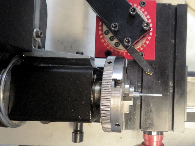
At upper right is a hand crank that moves a cutter on the front side of the valve away from the centerline at a 46o angle making the 92o included angle.
Sherlines don't have such a compound slide, but they do have an accessory (add-on) compound slide that I had bought probably 15 years ago. It wasn't until I tried to set it up that I realized I couldn't get anywhere near where I needed to get in order to cut the 46o angle. I can't recreate that geometry at all with the Sherline compound slide. Could I have done it if my blank was 3 or 3.5" long? I think so.
While thinking about this, I realized there was a way to cut this totally different from the book's; in fact, a couple of ways. One would be to cut a form-cutting tool. That would cut the 46o angle by cutting straight into the work. It also means making a fixture to hold a blank cutting tool that would keep the precise angle I need. The idea that appealed to me, though, would be to hold a tool I have at a different angle. I have several thread cutting tools, ground to a 60o tip that would just cut 60o if pushed in straight, but if I rotated the tool around the point, I could get it to cut 46o. Just set it in that compound slide and rotate it 14o (60-14=46).

I think I'm ready to move on to the next steps. The next step is to reduce the diameter of the entire stem to fit the testing bar I mentioned before. The procedure is to wrap some 220 grit carborundum paper around the stem and run the lathe piece at about 150 RPM while running the paper back and forth to cut evenly. The aim is a sliding fit in that test bar. Too tight and the valve springs won't pull the valves closed. Too loose and the intake stroke will suck air between the valve cage and the stem. It has to be the Goldilocks "just right" fit. Which is a lot easier to hit if you know what it feels like.
It's still not done. After that, I need to take it out of the chuck and drill the .040 through hole 0.109" from the end. At some point this valve gets ground against its valve cage to form the mating, sealing surfaces.
It would help if I knew what I was doing, but every part is a new encyclopedia worth of things to learn. Well, not every part. If I've made one before it's much easier to make the second and third.
It may be helpful in grinding the valve seats to hold the end of the valve stem in a loose drill chuck. Automotive manual valve grinding tools are usually plastic rods with rubber suction cup ends, intended to be spun between the palms of the hands. I could never get those to work very well.
ReplyDeleteIn the Book of Valve Making, the author talks about leaving it long so you can use the length to help you twiddle it back and forth in the valve seats to do the grinding. I like your idea of the drill chuck better.
DeleteSig, I use a female center to machine my valves. It is just a stub held in the tailstock with a hole the size of the stem. I relieve it on the cut side so my form tool will shape the underside of the head. Normal cuts can be taken at the start and then finer cuts as you did. A stainless valve with a 3/4" head and a 1/8" stem takes 40 minutes. Then after parting off, I reverse the valves and cut the 45* face by setting the compound at that angle.
ReplyDeleteI also use a drill to lap the valves.