Last month, I concluded part 1 by saying I was going to replace my roughly 15 year old 6m log periodic dipole array with a five element yagi. It will give me almost exactly 3 dB more gain – half an S-unit – so a good step up from the current performance.
The antenna I chose is from a company I hadn’t heard of before but which was talked about as being a good supplier on one of the radio forums I read, Directive Systems & Engineering, and the antenna is their model DSEJX5-50 (pdf datasheet). It’s currently in the box it was shipped in, in my shop. That’s the next big project; all of my antenna projects begin with the words, “when it cools off” and while it has been near record heat for the past week, it still beats anything from about April through October.
Since gain is the entire purpose of this sort of antenna, I thought a little discussion of how they’re designed and talked about would be worthwhile. You may see the gain referred to as dBd or dBi, and since the units are different, can you compare two different antennas? You may see gain patterns; are they directly comparable?
What do those dB abbreviations mean? The first one, dBd, is gain compared to a dipole, a half-wave antenna driven at the center and ordinarily considered to be in free space; that is, not affected by its surroundings. A dipole is a real antenna that you can build. The second, dBi, is gain compared to a theoretical antenna called an isotropic radiator. That word means the radiation is “the same in all directions” which gives you the hint that it’s theoretical and no such antenna can be built. A dipole has gain compared to an isotropic radiator, because its pattern is more donut-shaped than perfectly spherical, like the isotropic antenna, 2.15 dB more gain than the isotropic antenna to be exact, so we say 2.15 dBi. If two antennas are specified in the same units, just compare the two numbers and the bigger number means more gain. If one is in dBd and the other in dBi, subtract 2.15 from the dBi to convert to dBd. The gains in any particular direction are directly comparable, as are the beamwidths, and the front to back ratio.
Think about that from another direction for a second. If you compare any other kind of antenna to an isotropic, the numbers for gain in dBi are going to be bigger than if you compared it to a dipole and got the gain in dBd. That tells you that antenna gain will almost always be talked about in dBi instead of dBd. Bigger numbers sell better than smaller numbers.
Measuring antenna gain in the real world is difficult, especially the larger HF and low frequency VHF ones. A measuring receiver with a standardized antenna is mounted at some distance from the test antenna, and the amount of signal received from the test antenna is measured. Calibration is difficult without good laboratory equipment and standards. Due to the sizes involved this usually has to be done outdoors, with the test and receiving antennas mounted high above ground. By comparison, microwave antennas are easy; they’re typically measured indoors where the environment is easier to control, in rooms covered with absorptive foam to keep reflected signals from messing up the measurements. Standard antennas to help calibrate the measurement setup are much easier at microwave frequencies.
Most antenna gain values you’re going to come across will be from simulations in one of the various NEC programs (EZNEC, 4NEC, etc.) NEC is the Numerical Electromagnetics Code simulation approach developed by the US Lawrence Liverwurst National Lab. This code works by solving reduced electromagnetics equations, modeling the antenna as a collection of wire segments specified by their positions in space.
An interesting thing shows up in modeling that seems to be numerical “funny business” but is real. An antenna simulated over ground usually shows more gain than one in free space! What's happening is that the portion of the gain “balloon” that goes toward the ground in front of the antenna is reflected up to the main lobe and adds to it, actually adding gain.
This plot is a simulation of an antenna much like the one I’m putting up: a five element, six meter yagi, but not exactly the same one as I’m putting up. It’s modeled as being 30 feet above ground. The plot on the left is the free space pattern and gain, peaking at 9.91 dBi while on the right is the plot over a real ground available in the NEC simulator; note the gain is 15.42 dBi; that’s 5.51 dB greater gain in that one direction. Purely from the ground reflection.
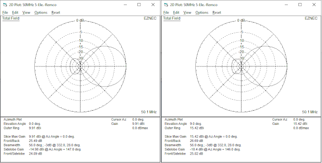
This can be seen in real operation, and is something that beginners at moonbounce communications try to use to their advantage by experimenting when the moon is just clearing the horizon. In the plot above, note the elevation angle (how high above ground maximum gain occurs) is 9.0 degrees. When the moon is 9 degrees above the horizon and if a good reflective ground is below the signal path for several wavelengths in its direction, that extra 5.5 dB gain can increase their station’s performance enough to enable contacts. You'll get better results over water - river, canal, bay, etc. - than over land. Here's where the real world conspires to make your life difficult (physics is such a bitch). Maybe instead of 5.5 dB improvement, you get one or two dB. It's still improvement.
I should point out that these NEC programs, (as you can see in the upper right, the program I used was EZNEC, which is about to go completely free by the end of the month) are analysis programs, not design or optimization programs. They can really help you with both design and analysis but won't give you designs; they'll just point out what the antenna can do. You can waste a lot of time trying things without some guidance. While I haven't worked with them, I've heard good things about a piece of software called Yagi Optimizer and another called YagiCAD.
Looks like a nice Yagi, SiG! I've had stuff from Directive Systems before, and it always met or exceeded my expectations.
ReplyDelete"US Lawrence Liverwurst National Lab"
ReplyDeleteSounds tasty! ;)
While I appreciate the physics and math behind antenna theory, it still seems like magic. Stakes pounded into the ground miles apart should not make a good TX/RX system, except that they do.
Thank you very much. Have you ever thought about running a course/school - for armed forces personnel - and anyone else who might have an interest quam high school students interested in "radio", old hams, like myself (1955) who are in need of a good refresher course, et al.
ReplyDeleteI can't say I've ever thought about it.
DeleteMy first thought is how would something like that work? Do you mean a class in person, or a Zoom?
I can write about all sorts of things, and could always use some ideas about what people would like to hear about. Drop me an email with anything you'd like to see.
SiGraybeard at gmail
Chuck beat me to a comment about Lawrence's sausage. Ha!
ReplyDelete(and Minecraft Chuck) thanks for catching my lame little joke.
DeleteI don't think I've ever NOT used that joke when talking about them with people. I see in that in the blog, though, I've been more formal and actually called them by their real name.
Time to stop that serious sh*t.
You bring up RF info/concepts that I have forgotten. The last 10 years of my employment was X and KA band Satcom earth stations from 4.6M to 9M dishes. It was boring but what the customer wanted.
ReplyDeleteThe last time I worked in Satcom was in the mid '80s. Mostly around 3 to 5m antennas, not the small (DirecTV-Style) dishes. They weren't around then and VSAT wasn't a thing. C band through Ku band.
Delete30 years later, I was designing weather radars at 10 GHz. Planar, slotted waveguide antennas.