When I say transmission lines, most of you will think of coaxial cables, which are the most common and most popular form of transmission lines in use today. Two points: first, they’re not the only kinds used in ham radio and in our shacks; second, transmission lines are also circuit elements widely used in radio frequency design. Having said that, let me go back and start from the basics. As always, this is to ensure we’re all on the same pages.
Transmission lines are what we think of when we want to get a signal from one point to another in our shacks or around our yards to get to antennas. Ideally, you’d want no loss of signal and you’d want perfect shielding to keep the signal from radiating minute amounts of power into other circuits. The strong point of coaxial cables is that they’re good at both of these. A diagram of a typical cable shows the important dimensions.
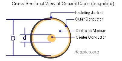
The loss in the cable is more dependent on the overall diameter than on the exact construction; for example, details like whether the "dielectric medium" (insulator) is Teflon or polyethylene. Larger cables have less loss. Loss goes up as frequency goes up in any cable. The shielding efficiency of single shielded coaxial cables is on the order of 50 to 60 dB (1/100,000 to 1/1,000,000 of the signal escapes – which can still be a problem in sensitive systems). In those cases, double shielded cables (for example, RG-214 vs. RG-213) or cables with solid copper jackets (sometimes called hard line) get more shielding, with the rigid (solid copper jacket) cables providing shielding 1 to 10 million times better; leakage in the 10-13 range.
The impedance of the cable is set by the dimensions it’s built to, but ordinarily you won’t build coaxial cables, you’ll buy the cable.

Where epsilon r is the dielectric constant of the insulator, D is the inside diameter of the outer shield and d is the outside diameter of the inner conductor.
The other common type of transmission line is formed by two parallel conductors. These are available in different impedances, and the impedance of a parallel conductor line is given by a very similar equation.
Note that 276 is 2 times the 138 in the coax equation. This equation uses k for the epsilon r used in the coax equation.
The most common parallel conductor line impedance is probably 300 ohms; that’s usually a plastic insulated ribbon with thicker ribs on the edges, each carrying one wire, and called twin-lead. There’s a higher impedance line called ladder line, which is sometimes constructed as the name implies: two wires with stick-like insulators between them so that it resembles a ladder. There are 450 and 600 ohm ladder lines, a couple of examples from
DX Engineering.
Coaxial cable is easier to run around and get through windows and walls, but parallel conductor lines can offer better impedance transformations and allow more broadband antennas. Coaxial cable has a bend radius that needs to be respected, but I find that easy to live with in Real Life. Parallel conductor lines generally offer lower loss than coax, as this graph from the ARRL handbook shows, but are said to be more affected by rain and water on the lines. Pick a frequency along the horizontal axis and go vertically to the transmission line you’re using to find the attenuation (in dB/100 ft). You’ll note that the lowest loss is in the open wire lines at the bottom. Higher is worse on this graph.
Graph with notation on it from
here.
It might be worth pointing out that these are typical numbers and that if you’re going to buy a coaxial cable, it can be worth researching the exact part number from the manufacturer you’re buying from. If you can know that. They’ll often give a table of losses in dB/100ft, like the chart here, that they guarantee their cable for.
Since the theme of coaxial cables is “easier to live with and work with,” it’s worth mentioning connectors. Over the years, manufacturers have migrated from soldered-on connectors to those that are crimped on. This is because crimped on connectors have gotten better over the years and generally offer higher quality (higher repeatability) in the assembled connectors. Much as you hardly see soldered on power connectors anymore, and they’re virtually all crimped, the same trend is in the RF world. My station is still exclusively soldered-on connectors, but if I was starting over, or anticipating doing a lot of cable replacement, I’d seriously look at buying crimp on coax connectors and a good crimping tool.
There’s a world of “connector nerds” out there who are against the use of the so-called UHF connectors (PL-259 plugs and SO-239 sockets) and it’s true that if you apply that equation for the impedance of a coaxial cable to the dimensions of UHF connector you come with a lower impedance than 50 ohms (around 30, IIRC). The argument, undeniably true, is that difference causes an impedance bump on the transmission line that decreases performance.
I think it's good to ask yourself if that matters. My approach is to always think in terms of electrical length and how big the impedance bump is. The length of a mated pair of UHF connectors is around 1.3 inches. I’d like to make sure that’s under 1/20 wavelength – and 1/20 wave is admittedly arbitrary and probably because I can’t recall the last time I saw a bump that small that mattered. The formula for the length of a quarter wave vertical, in feet, given f in MHz is 234/f; 1/20 wave is 1/5 of that, and since 1.3 inches is 0.1083 feet, that gives us

solving for f, we find f has to be 432 MHz before a mated UHF connector pair is 1/20 wavelength long. I’ve long used UHF connectors through 6m (50-54 MHz) and virtually every commercial 2m (144-148 MHz) I’ve seen has a UHF connector on it. Many commercial ham radios that cover the 420 to 450 MHz band also use UHF connectors. I would prefer to have N connectors for 2m and up, but will accept UHF. On 145 MHz, 1/20 wave is 3.87 inches, so 1.3 is just about 1/60 wave. That’s a pretty small bump.
While it's true the twin lead transmission line is trickier to work with than coaxial cable, there are some multi-band antennas, like a G5RV and several other doublet antennas, that pretty much require it.
The antennas typically still require an antenna tuner, and tuners that will handle the twin lead are both harder to find and more expensive. I've seen examples where people do a balun (balanced to unbalanced transformer) outdoors so that the twin lead is converted to coax and a single coaxial line comes into the house. That may allow you to tune your multi-band doublet with a coaxial tuner inside the house. It could give the best of both worlds of the twin lead where you need it and the ease of routing coax where you need that. I've read of it being done, but never tried it.


I don't worry about "UHF" connectors on 70cm, either, and pretty much for the same reasons.
ReplyDeleteI also run 75 Ohm RG6QS for all my receive-only antennas. It lower loss than equivalent sized 50 Ohm coax, has better shielding, and gives a slight mismatch resulting in a 1.5:1VSWR, perfectly acceptable for Real World use. Anybody who start screaming that I'll have "Excess Loss Due VSWR" just shows they don't know how to read and interpret the published tables.
I've seen people do the coax-balun-ladder-line-balun-coax install before on very long runs, and it works, but I never ran the numbers to see if the loss reduction was worth the extra expense.
Now there's an argument for a two port network analyzer like one of those NanoVNAs. If you have coax to balun to ladder line to balun to coax, you can measure the loss. Otherwise, it's hard to know how much loss you get end to end.
DeleteI've never had a big enough lot to have to worry about it.
Just a week ago I helped put in a station with coax thru the wall, balun and window line to the antenna. Works fine.
ReplyDeleteA variant for thru the wall balanced line is using a pair of coax cables, shields grounded and the balanced line tied to each center conductor. In my station, I use it to bring 600 ohm ladder line inside to a 1:1 balun and tuner. I use a pair of 75 ohm coax lines (originally part of a satellite TV system) about a meter in length. So I have a 150 ohm balanced line "bump" in the system, but if it has any effect, the tuner takes it out. Certainly works well at HF.